A step lap transformer core uses a controlled sequence of overlapping lamination joints to guide magnetic flux across the limb-to-yoke connection more gradually than a single abrupt joint. The concept is widely used in CRGO laminated transformer cores, but the term “step lap” by itself does not define the complete joint geometry. The number of steps, overlap or lap length, lamination sequence, steel grade, miter angle, packet grouping, and stacking accuracy all influence how the joint performs.
For transformer manufacturers and core buyers, the practical issue is not whether step-lap construction is generally useful. The real issue is whether the exact step lap transformer core shown on the drawing can be manufactured and assembled consistently. A good design can lose much of its intended advantage if laminations are stacked in the wrong order, mixed between packets, damaged at the edges, clamped unevenly, or built from material that does not match the approved magnetic design.
This guide explains how step-lap joints work, how they differ from simple 45° mitered joints, which drawing fields should be controlled, what assembly checks matter, and what buyers should include in an RFQ before laminated-core production begins.
What Is a Step Lap Transformer Core?
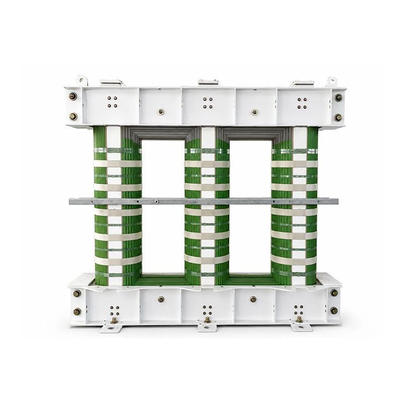
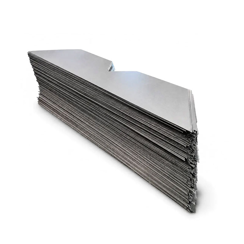
A step lap transformer core is a laminated magnetic core in which successive lamination layers are intentionally offset at the joint. Instead of all sheets meeting at exactly the same line, the joint is distributed over several positions.
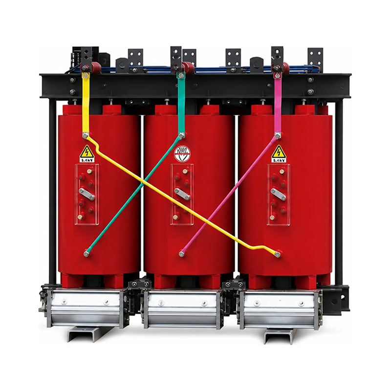
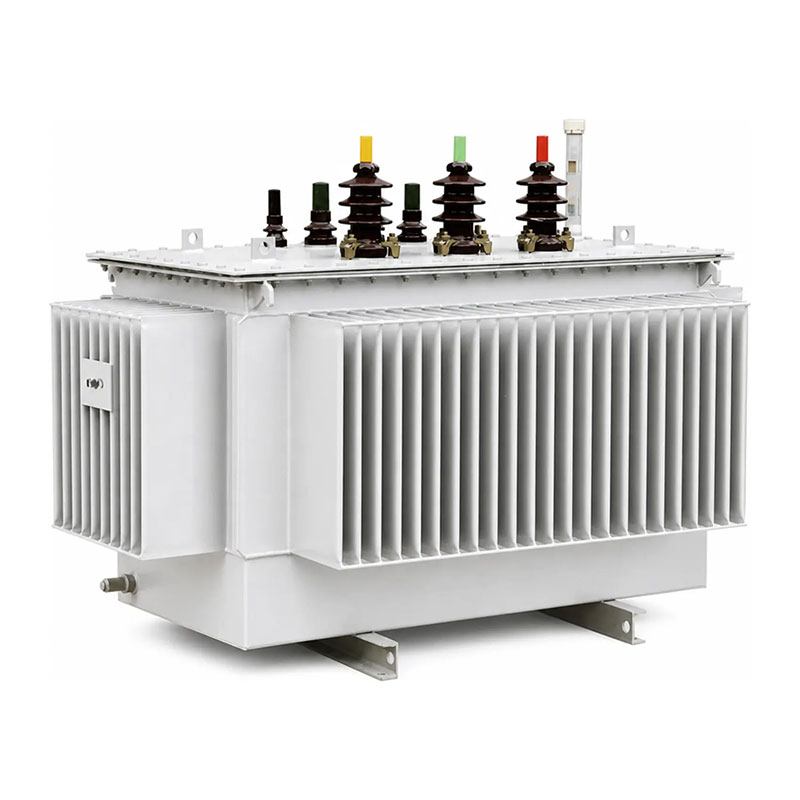
Prennox currently lists 45° mitered, step-lap, and multi-step-lap configurations for both its قلب CRGO الرقائقي للمحولات من النوع الجاف و قلب مصفح HI-B CRGO للمحولات المغمورة بالزيت. The exact joint design is manufactured according to the approved transformer drawing and magnetic requirements.
The step-lap arrangement is used because the limb-yoke joint is one of the locations where flux direction changes and where local reluctance, leakage flux, and magnetizing effects can become more significant. Distributing the joint across several lamination layers can help smooth the magnetic transition when the design is optimized correctly.
45° Mitered and Step-Lap Describe Different Things
One of the most common specification mistakes is treating “45° mitered” and “step-lap” as interchangeable terms.
A 45° miter describes the angle of the lamination end. A step-lap describes how successive layers are offset relative to one another at the joint. A core can use 45° mitered laminations and also use a step-lap sequence. It can also use a 45° full-mitered lamination set without a step-lap sequence if the approved design calls for that arrangement.
This distinction matters because a step lap transformer core drawing must define more than end angle. It should show the number of step positions, lap or overlap dimension, sequence of different lamination lengths, layer order, and any repeating packet pattern.
Prennox’s existing 45° Full-Mitered CRGO Lamination Set Without Clamps is a good example of why supply form and joint definition must remain separate. That product is supplied as a lamination set without clamps, and step-lap should only be assumed when it is actually shown in the customer drawing or manufacturing specification.
Why Step-Lap Joints Affect Magnetic Flux Distribution
At any transformer core joint, magnetic flux must cross from one lamination group into another. If the joint is concentrated at one position, local flux crowding and flux deviation from the rolling direction can increase.
A step lap transformer core spreads the joint transition across several layers. The magnetic path therefore changes progressively rather than abruptly. Research on transformer-core joints has shown that lap length influences local magnetic flux density distribution and no-load loss, demonstrating that overlap geometry is a real design parameter rather than a cosmetic detail.
However, the relationship is not “more overlap is always better.” The optimum depends on magnetic induction, material grade, number of steps, core geometry, and joint construction. Published research has also shown that step number and overlap can affect core noise.
For procurement, the lesson is simple: do not invent a generic lap length or copy a step-lap pattern from another transformer. Use the approved electromagnetic design.
The Number of Steps Must Be Defined on the Drawing
A step lap transformer core can use different numbers of step positions. Five-step and other multi-step arrangements are common in research and industry, but there is no single step count that is optimal for every core.
The number of steps affects the number of different lamination lengths and the sequence required during stacking. More step positions can create a smoother joint transition, but they also increase cutting and stacking complexity.
ال step lap transformer core drawing should therefore define the step count explicitly. If the buyer is purchasing loose laminations, each different length should have a clear piece identification so the factory can reconstruct the intended sequence.
Lap Length or Step Overlap Is a Critical Joint Parameter
Lap length describes the offset between successive joint positions. This value changes the physical distribution of the joint and can influence local magnetic flux and loss behavior.
Recent IEEE-published work on step-lap joints identifies lap length as one of the critical parameters affecting magnetic flux density distribution and no-load losses. The reported results also show that changing lap length can affect losses differently at different magnetic flux densities.
This reinforces an important purchasing rule: a step lap transformer core should not be approved from a generic note such as “standard step lap.” The actual overlap dimension should be controlled by drawing or by an agreed supplier-designed joint that has been technically approved.
| Joint parameter | لماذا يهم | What should be controlled |
|---|---|---|
| Miter angle | Defines the lamination-end geometry | Cut angle and dimensional tolerance |
| Number of steps | Defines how many joint positions are distributed across the stack | Approved step count and repeating sequence |
| Lap / overlap length | Influences magnetic transition and joint geometry | Approved offset dimension |
| Lamination sequence | Controls correct reconstruction of the designed joint | Piece number, layer order and packet sequence |
| Packet thickness | Affects cross-section and step repetition | Number of laminations or physical thickness per packet |
| Material grade | Changes magnetic properties under the same geometry | Approved CRGO grade and thickness |
CRGO Grade and Joint Design Must Be Evaluated Together
A step-lap joint does not operate independently from the electrical steel used to build it. Conventional CRGO, Hi-B high-permeability GOES, and domain-refined grades can behave differently under the same nominal geometry.
Prennox’s laminated-core pages currently list conventional CRGO or Hi-B options for dry-type cores and selected Hi-B grades for oil-immersed cores. Steel thickness is typically 0.23, 0.27, or 0.30 mm depending on the selected grade.
في أ step lap transformer core, the buyer should therefore approve the material grade, thickness, joint design, and magnetic-performance requirement together. A step-lap sequence developed around one grade should not automatically be assumed to deliver the same result if the material is changed.
السابق درجات الصلب CRGO وتقارير الاختبار guide explains how grade, magnetic test conditions, and certificates should be reviewed before core production.
Step-Lap Joints Do Not Guarantee a Fixed Loss Reduction
Step-lap construction is often associated with improved no-load performance, but buyers should be careful with claims such as “step lap reduces loss by X%.”
The actual performance of a step lap transformer core depends on CRGO grade, flux density, step count, overlap, cutting quality, burr, lamination alignment, clamping pressure, packet geometry, and the finished transformer design.
Published research supports the importance of step geometry, but it also shows that performance changes with magnetic induction and other design variables.
A supplier should therefore guarantee only the magnetic performance that is actually agreed and testable under the specified conditions. A general step-lap label is not a substitute for a core-loss or transformer no-load-loss requirement.
Cutting Accuracy Is Essential for Consistent Step Geometry
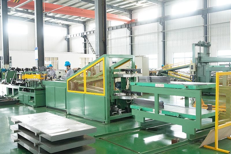
A step-lap sequence relies on multiple lamination lengths. If one length is cut incorrectly, the joint positions shift and the intended overlap pattern is disturbed.
لهذا السبب،, step lap transformer core manufacturing needs controlled strip width, lamination length, miter angle, step offset, and piece identification. Automated cutting lines can improve repeatability, but the quality requirement still comes from the approved drawing.
The core supplier should also control burr and edge quality. Excessive burr can affect stacking, create interlaminar contact, and change the physical joint condition.
Burr Direction Should Be Controlled During Stacking
Shearing and miter cutting can leave a small burr on the cut edge. The transformer-core drawing or assembly procedure should define how burr direction is handled during stacking.
ل step lap transformer core, inconsistent burr direction can change local contact between laminations and can create uneven stack build around the joint.
IEC 60404-9 provides methods for measuring burr height and other geometrical characteristics of electrical steel strip and sheet. Buyers who need a controlled burr limit should define a measurable acceptance value rather than using a vague “burr-free” requirement.
Lamination Identification Is Critical for Loose Step-Lap Sets
A fully assembled core can hide much of the internal stacking sequence from the customer. A loose lamination set cannot.
If a buyer receives a step lap transformer core as separate pieces, the supplier should provide enough identification to reconstruct the approved sequence correctly. This may include part numbers, length groups, packet labels, orientation marks, stacking diagrams, and bundle order.
The risk is highest when several lamination lengths differ by only a small step dimension. A mix-up can produce a joint that looks generally correct but no longer follows the intended electromagnetic design.
Packet Thickness and Layer Sequence Need Consistency
Many step-lap cores repeat a defined number of laminations at each step position. The number of sheets per packet or the physical packet thickness can affect the magnetic transition and final core cross-section.
A step lap transformer core assembly instruction should therefore define how many laminations belong at each position before the sequence moves to the next step.
If packet thickness changes unintentionally because of mixed steel thickness, missing sheets, coating variation, or stacking errors, the joint geometry can shift even when the individual lamination lengths are correct.
Stacking Sequence Should Be Checked Before Final Clamping
The best time to find a step-lap assembly error is before the core is fully closed and clamped.
عملي step lap transformer core inspection can compare the visible joint sequence against the stacking diagram after each major packet group. The team should verify piece identification, step direction, overlap, packet count, joint symmetry, window dimensions, and stack thickness before final clamping.
Once the step lap transformer core is fully compressed, correcting a sequencing error can require substantial disassembly and may damage laminations during rework.
| Assembly check | ماذا تتحقق | Typical error prevented |
|---|---|---|
| Piece identification | Correct lamination length and packet number | Wrong step sequence |
| Joint orientation | Correct miter and step direction | Reversed joint pattern |
| Lap dimension | Visible overlap matches approved drawing | Flux transition differs from design |
| Packet count | Correct number of sheets per step | Uneven joint build |
| Stack thickness | Measured against approved requirement | Core cross-section or window mismatch |
| Window geometry | Width, height and diagonals | Winding fit problems |
| حالة السطح | No severe scratches, rust, chips or trapped metal particles | Interlaminar and assembly defects |
Clamping Pressure Can Influence the Finished Core
After stacking, the core is restrained mechanically. Clamping is necessary for dimensional stability and transformer assembly, but excessive or uneven mechanical stress can affect electrical steel behavior and create noise or loss changes.
A step lap transformer core should therefore use the approved clamping structure and assembly method. The supplier should not simply increase clamping pressure to compensate for a poorly aligned stack.
If the product is supplied as loose laminations without clamps, the customer assumes more responsibility for final core build and mechanical assembly. This is why the purchase order must clearly state whether clamps, frames, tie rods, fixtures, or other assembly hardware are included.
Step-Lap Geometry Can Also Affect Core Noise
Transformer core noise is influenced by magnetostriction, flux density, material grade, joint design, clamping, and structural vibration. Step-lap geometry can therefore affect sound as well as loss.
Research on model step-lap cores has shown that step number and overlap influence measured noise, and that results depend on magnetic induction and material condition.
This does not mean every step lap transformer core should use the same step count or overlap to achieve low noise. The transformer designer should optimize the joint together with material grade, flux density, core size, and mechanical structure.
Incoming Inspection Should Match the Purchased Supply Form
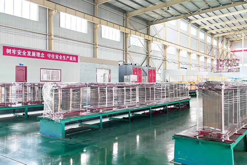
If the buyer purchases an assembled laminated core, incoming inspection should focus on final dimensions, window geometry, stack thickness, joint configuration, visible alignment, surface condition, identification, and agreed magnetic test records.
If the buyer purchases a loose step lap transformer core lamination set, incoming inspection must go deeper. Piece counts, length groups, strip widths, step sequence, orientation, burr, package identification, and stacking instructions become essential.
الموجود متطلبات الرسم الأساسية للمحول guide explains how drawing scope changes between loose lamination sets and assembled cores.
Common Step Lap Transformer Core Mistakes
Assuming 45° Mitered Automatically Means Step-Lap
It does not. Miter angle defines the cut geometry, while step-lap defines how successive lamination layers are offset.
Using “Standard Step-Lap” Without a Drawing
Different designs use different step counts, overlap lengths, packet structures, and sequences. A step lap transformer core needs an approved joint definition.
Mixing Lamination Length Groups During Assembly
Even small piece-length differences matter because they create the step sequence. Clear labeling and stacking instructions are essential for loose sets.
Ignoring Burr and Edge Condition
Excessive burr or damaged coatings can change stacking behavior and interlaminar contact at the joint.
Expecting a Fixed Loss Improvement From Step-Lap Alone
Loss depends on the full magnetic and manufacturing design. Step-lap is one variable, not a standalone performance guarantee.
What to Include in a Step Lap Transformer Core RFQ
مفيد step lap transformer core RFQ should include the core drawing, transformer application, CRGO grade or target magnetic properties, steel thickness, window dimensions, limb and yoke dimensions, stack thickness, miter angle, step count, lap or overlap dimension, packet sequence, punching/notching where required, supply form, quantity, and inspection requirements.
For loose lamination sets, add individual strip widths, lamination lengths, piece numbering, bundle identification, stacking sequence, clamps included or excluded, and packing instructions.
For assembled cores, define final dimensional tolerances, joint inspection points, magnetic performance requirement where applicable, clamping scope, lifting/handling requirements, and the final inspection report expected.
If the supplier is expected to optimize the step-lap design rather than simply manufacture to the drawing, that engineering responsibility should be agreed before quotation.
What Prennox Needs Before Reviewing a Step-Lap Core
For laminated dry-type cores, Prennox requests the core drawing, main dimensions, material requirement, steel thickness, joint configuration, supply form, and quantity. Its current product page lists 45° mitered, step-lap, and multi-step-lap joint options and conventional or Hi-B CRGO material choices.
For oil-immersed laminated cores, the same drawing-based review applies, with Hi-B CRGO grade selected according to the required magnetic performance and transformer design.
If the core is being ordered as loose laminations, review the 45° Full-Mitered CRGO Lamination Set Without Clamps page and make sure the purchase order states whether a step-lap sequence is required. Drawings can also be sent through the صفحة الاتصال for technical review before quotation.
خاتمة
A step lap transformer core is defined by the complete joint sequence, not by one label. Miter angle, number of steps, lap length, lamination length groups, packet thickness, CRGO grade, burr condition, stacking order, clamping, and assembly accuracy all contribute to the final joint.
Step-lap construction can help manage flux transition at transformer-core joints, but it should never be treated as a fixed loss- or noise-reduction percentage. Published research shows that overlap, step number, material, and magnetic induction all influence the result.
For buyers, the most important controls are a clear drawing, controlled piece identification, defined supply form, measurable inspection criteria, and verification of the joint sequence before final clamping. Those steps make the design easier to reproduce and reduce the risk that a theoretically sound joint is lost during production.
الأسئلة الشائعة
What is a step lap transformer core?
A step lap transformer core is a laminated core in which successive lamination layers are offset at the limb-yoke joint so the joint transition is distributed over multiple positions rather than concentrated at one line.
Is a 45° mitered core the same as a step-lap core?
No. The 45° miter describes the lamination-end angle. Step-lap describes the offset sequence between successive lamination layers. A core can use both features together, but they are not the same design parameter.
Does step-lap always reduce transformer core loss?
Step-lap can improve magnetic transition at the joint, but the actual result depends on overlap, number of steps, CRGO grade, flux density, cutting quality, stacking, and clamping. No fixed percentage improvement should be assumed without validated data.
What should be checked during step-lap core assembly?
Verify piece identification, lamination length groups, miter direction, step sequence, lap dimension, packet count, stack thickness, window geometry, burr direction, surface condition, and clamping alignment before final assembly.
What information should be included in a step lap transformer core RFQ?
Provide the core drawing, CRGO grade or magnetic target, steel thickness, window and core dimensions, miter angle, step count, lap length, packet sequence, supply form, quantity, inspection requirements, and—if supplied loose—piece identification and stacking instructions.