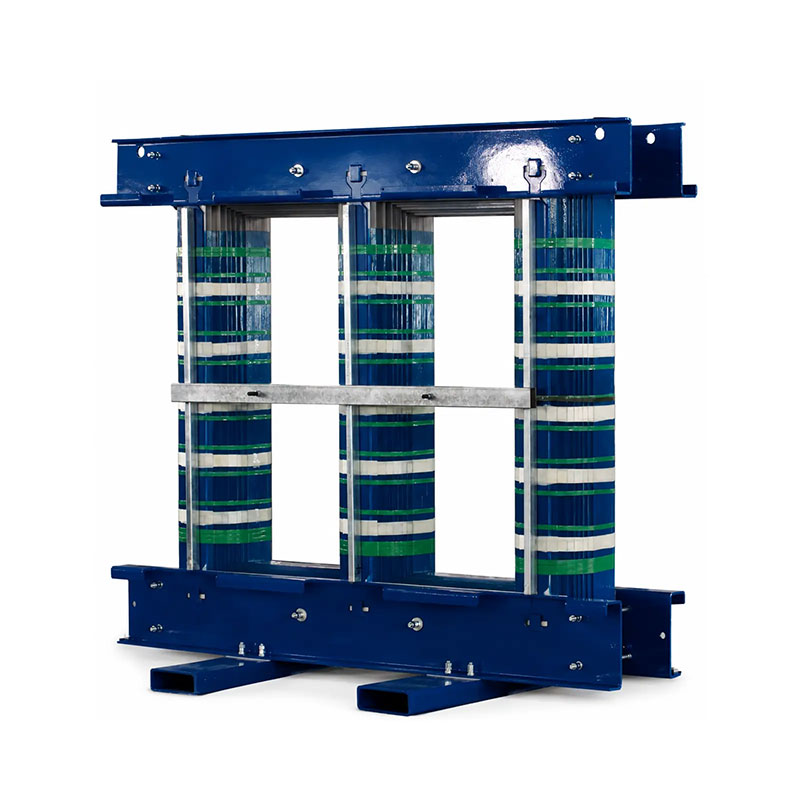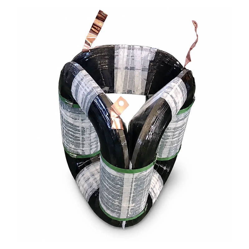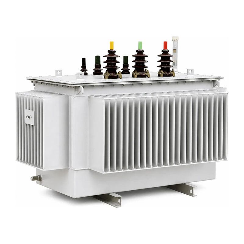
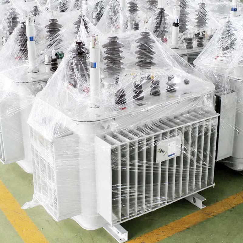
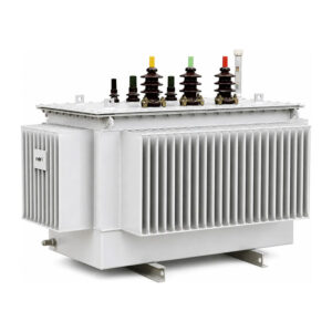
This is a three-phase oil-immersed distribution transformer built with an iron-based amorphous alloy core. Compared with a conventional grain-oriented electrical steel transformer of comparable rating and specification, the amorphous alloy core is primarily selected to reduce no-load loss. This makes the transformer suitable for systems that remain energized continuously or operate for long periods under light or variable loads.
The documented series covers a reference capacity range of 30–1600kVA for the 10kV class, with GB series S15 / S21 / S25 available where applicable. The final tank construction, winding arrangement, guaranteed losses and accessories are confirmed according to the approved project specification, and export configurations can be reviewed against IEC 60076 or another specified project standard.
A distribution transformer spends almost its entire life connected to the grid. Even when the load side draws little or no power, the core stays magnetized and continues to consume energy. That standing consumption is the no-load loss, and over a service life of twenty years or more it adds up to a very large electricity bill — one that the utility or the end user pays whether the transformer is working hard or idling.
The amorphous alloy oil-immersed distribution transformer addresses exactly this part of the operating cost. By replacing the conventional grain-oriented silicon steel core with an iron-based amorphous alloy core, the no-load loss is reduced to a small fraction of the conventional level, while the oil-immersed, hermetically sealed construction keeps the active part protected and maintenance demand low. The corrugated tank walls accommodate changes in oil volume during operation, so no separate conservator is required.
This transformer type is therefore most often specified for rural distribution networks, utility feeders, industrial parks and any distribution point that stays energized around the clock but carries light or strongly variable loads for much of the day. It is also widely used in distribution-system efficiency improvement projects, where the energy saved on no-load loss is the direct justification for the investment.
If your network is lightly loaded for long periods — night-time hours, seasonal loads, agricultural feeders, standby or continuously energized local systems — the no-load loss dominates the total loss picture. That is the operating profile where an amorphous alloy core delivers its real value. If your transformer runs near rated load almost all the time, the load loss matters more, and selection should be based on the guaranteed loss data of both alternatives rather than the series designation alone.
Electrically, an amorphous alloy transformer works exactly like any other oil-immersed distribution transformer. Alternating current in the primary winding creates an alternating magnetic flux in the closed core, and that flux induces a voltage in the secondary winding according to the turns ratio. The transformation itself is unchanged — what changes is how much energy the core wastes while doing its job.
Every time the flux in the core reverses, the magnetic domains inside the core material have to re-orient, and that re-orientation consumes energy (hysteresis loss). At the same time, the changing flux induces small circulating currents inside the core laminations (eddy current loss). Together these two components make up the no-load loss — the energy the transformer draws from the grid even with its secondary side open.
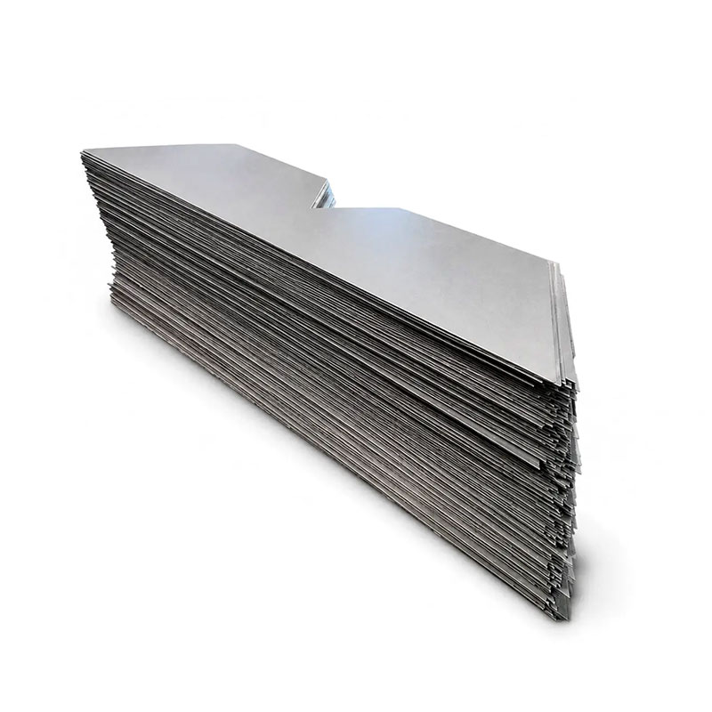
Amorphous alloy is produced by cooling molten metal so rapidly that the atoms freeze in a disordered, glass-like arrangement instead of forming a regular crystal lattice. This disordered structure gives the material two properties that matter directly for no-load loss:
The result is a core whose no-load loss is typically 60–70% lower than a comparable conventional silicon steel design of older generations, and still clearly lower than modern high-grade silicon steel designs. The trade-off is that amorphous ribbon is thin, brittle and sensitive to mechanical stress, so the core construction, clamping and assembly process must be designed specifically for this material. That is why the core construction of each unit is confirmed according to the approved design rather than treated as an interchangeable commodity part.
Buyers often ask a simple question: is an amorphous alloy transformer always the better choice? The honest answer is that it depends on the load profile and the electricity price. The table below summarizes the practical differences.
| Item | Amorphous Alloy Core | Grain-Oriented Silicon Steel Core |
|---|---|---|
| No-load loss | Very low — the main reason to choose this core | Higher; depends on steel grade and design generation |
| Load loss | Comparable for the same energy-efficiency grade | Comparable for the same energy-efficiency grade |
| Initial cost | Higher (material and core-processing cost) | Lower |
| Best load profile | Continuously energized, light or variable loads | High and steady load factors |
| Payback logic | No-load energy savings repay the price difference | Lower first cost; savings case is weaker at low load |
| Mechanical sensitivity | Core is stress-sensitive; handling and transport rules must be followed | More tolerant of mechanical stress |
In short: the amorphous core wins where energization hours are high and the average load factor is low. The savings are realized automatically every hour the transformer is connected, with no change in operating practice required from the user.
The following table shows the reference configuration of this series. Values marked as project-specified are confirmed in the approved technical data sheet for each order.
| Parameter | Available Configuration |
|---|---|
| Type | Three-phase amorphous alloy oil-immersed transformer |
| Core material | Iron-based amorphous alloy |
| Core construction | According to the approved design |
| Reference capacity range | 30–1600kVA for the documented 10kV series |
| Rated voltage | Specified for each project |
| Frequency | Project-specified (50Hz / 60Hz) |
| GB series | S15 / S21 / S25, where applicable |
| Complete model designation | Confirmed according to the selected construction |
| Guaranteed losses | Confirmed in the approved technical data sheet |
| Vector group | Dyn11, Yyn0, Yzn11 or project-specified |
| Cooling method | ONAN |
| Voltage regulation | Off-circuit tapping |
| Tapping range | Project-specific |
| Tank | Hermetically sealed corrugated steel tank |
| Installation | Outdoor or project-specified |
| Accessories | Configured according to the approved specification |
Under the Chinese GB energy-efficiency framework, distribution transformers are grouped into series by their loss levels. The amorphous alloy core is most commonly applied in the higher-efficiency series, where the no-load loss requirement is the most demanding:
| Series | Positioning |
|---|---|
| S15 | Established low-loss amorphous series for general distribution upgrades |
| S21 | Higher energy-efficiency grade meeting the newer GB 20052 level requirements |
| S25 | Top efficiency grade for projects with the strictest no-load loss limits |
For export projects, the loss guarantee is usually written directly into the contract technical data sheet (for example in watts at rated voltage and frequency) rather than referenced by GB series. Tell us the loss limits your grid code or tender requires, and the design will be confirmed against them.
Chinese-market configurations can be reviewed against the applicable requirements of GB 1094, GB/T 6451, GB/T 25446 and GB 20052. Export configurations can be reviewed against IEC 60076 or another specified project standard. Final compliance depends on the approved design, guaranteed values and agreed test documentation.
Every unit is verified before dispatch. Routine tests may include:
Type tests, special tests (such as temperature-rise, sound level or lightning impulse) and third-party inspection can be agreed before production when required by the project or tender. Test reports are delivered with the unit documentation.
A distribution transformer is energized roughly 8,760 hours per year. The no-load loss runs for all of them. Cutting that loss by well over half compared with older conventional designs converts directly into saved kilowatt-hours — savings that repeat every year for the whole service life and that grow in value as electricity prices rise.
The hermetically sealed corrugated tank keeps the insulating oil away from air and moisture. There is no conservator and no breather to service. For utilities and industrial users with hundreds of transformers spread across a territory, this removes a whole category of routine maintenance work.
Voltage ratio, vector group, tapping range, accessories, corrosion protection and installation arrangement are all confirmed against your project specification. What you receive is documented against the approved technical data sheet — the same values the routine tests verify before shipment.
Many grid codes, government tenders and utility procurement rules now set minimum efficiency or maximum loss levels. The amorphous alloy series makes it straightforward to meet strict no-load loss limits, and the energy-saving case is easy to document for internal approval.
This series is designed for distribution-level applications where the transformer stays connected for long hours and the load is often light or variable:
The operating-cost benefit of an amorphous alloy transformer depends on its guaranteed losses, load profile, annual operating hours and local electricity cost. Selection should therefore be based on the approved no-load and load loss data rather than the series designation alone. A practical selection process looks like this:
If you share your load profile and electricity price with us, we can run the payback comparison between the amorphous design and a conventional design for your specific case before you decide.
Because the amorphous core is sensitive to mechanical stress, correct handling matters more than with conventional transformers. Follow these practical rules:
| Symptom | Likely Cause | Action |
|---|---|---|
| Abnormal hum or vibration noise | Loose fastening, overvoltage, or mechanical shock during transport | Check supply voltage and external fastening first; if noise persists, arrange a no-load loss test before further operation |
| Oil traces on tank or bushings | Sealing surface damage or gasket aging | Do not open the sealed tank on site; contact the manufacturer for seal inspection and repair |
| Higher-than-expected temperature | Sustained overload, blocked cooling surfaces, high ambient temperature | Measure the actual load current, clean the corrugated walls, improve ventilation; reduce load if it exceeds rating |
| Measured no-load loss above the guarantee | Core suffered mechanical stress, or measurement setup error | Re-verify with a calibrated test setup at rated voltage and frequency; contact the manufacturer with the test record |
| Protection trips at energization | Inrush current, wrong tap position, or wiring error | Check tap setting and wiring against the nameplate; inrush is normal — coordinate protection settings accordingly |
Around the world, minimum energy performance standards for distribution transformers have been tightening steadily. The logic is simple: transformers are everywhere, they run continuously for decades, and their standing losses are a meaningful share of total grid losses. Regulators in China, the European Union and many other markets now set mandatory loss limits, and grid operators increasingly buy on total cost of ownership rather than lowest purchase price.
This trend directly favors amorphous alloy designs. What used to be a premium option for efficiency-conscious buyers is becoming the standard answer wherever no-load loss limits are strict. For project owners, specifying a low-loss transformer today is also protection against future energy prices: every kilowatt-hour saved is worth more each year the tariff rises. When planning a network upgrade or a new industrial connection, it is worth checking not only today’s minimum standard but also the direction of the next revision — a transformer bought now will still be in service when it arrives.
The saving equals the difference in no-load loss multiplied by the hours the transformer is energized — typically all 8,760 hours per year. Because amorphous cores cut no-load loss by roughly 60–70% compared with older conventional designs, the annual saving on a mid-size unit is substantial and repeats every year of service. Share your capacity and tariff with us and we will calculate the exact figure for your case.
It works fine electrically, but the economic case is strongest where loads are light or variable. If your transformer runs near rated load most of the time, load loss dominates, and you should compare the guaranteed loss data of both options before deciding. We can supply both and will tell you honestly which one suits your profile.
Yes. Export configurations can be reviewed against IEC 60076 or another specified project standard. Tell us the standard your tender or grid code references, and the design, guaranteed values and test documentation will be confirmed against it.
Rated capacity, voltage ratio, frequency, vector group, tapping range, guaranteed loss requirements, applicable standard, installation conditions, required accessories, quantity and destination. The more complete your specification, the faster and more accurate the quotation.
Routine maintenance is minimal. The hermetic seal keeps the oil isolated from air, and the corrugated walls handle oil expansion. Normal in-service work is periodic visual inspection, connection checks and cleaning of the cooling surfaces — no breather replacement, no conservator checks.
The ribbon itself is brittle, which is why the core construction and clamping are specifically designed for this material, and why handling rules must be followed. Units are packed for export transport, and we recommend checking the unit on arrival and reporting any transport damage before installation so it can be assessed properly.
Yes. Type tests, special tests and third-party inspection can be agreed before production when required. This is common for utility tenders and export projects — just include the requirement in your inquiry so it is planned into the production schedule.
The documented series covers 30–1600kVA for the 10kV class. Other voltage levels and capacities can be discussed for specific projects — send us your requirements and we will confirm feasibility and lead time.
To prepare an accurate quotation, please provide:
Not sure about some of the items above? Send us what you have — our engineering team will help you complete the specification and recommend the configuration that fits your load profile and budget.