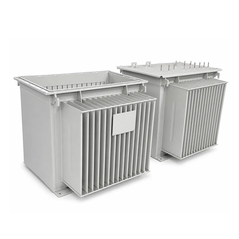
Transformer tank corrugation design affects far more than the external appearance of an oil-immersed transformer tank. Corrugated walls can increase heat-transfer area, contribute to oil-volume compensation in sealed designs, influence tank stiffness and deformation, change the external envelope, and affect welding, coating, transport, and leak-test behavior.
For transformer manufacturers and project engineers, the key challenge is balancing thermal, mechanical, and fabrication requirements. Deeper or more closely spaced corrugations may increase geometric surface area, but they also change tank width, forming behavior, air flow, oil-side circulation, structural flexibility, and coating access. A design that looks thermally attractive may not be the easiest or safest structure to fabricate, transport, or test.
This guide explains how to approach transformer tank corrugation design before fabrication. It focuses on pitch, depth, panel width, plate thickness, oil expansion, cooling, pressure and vacuum requirements, welding, coating, dimensional control, leak testing, and the RFQ inputs that should be confirmed before the tank drawing is released.
Why Transformer Tank Corrugation Design Is a System Decision
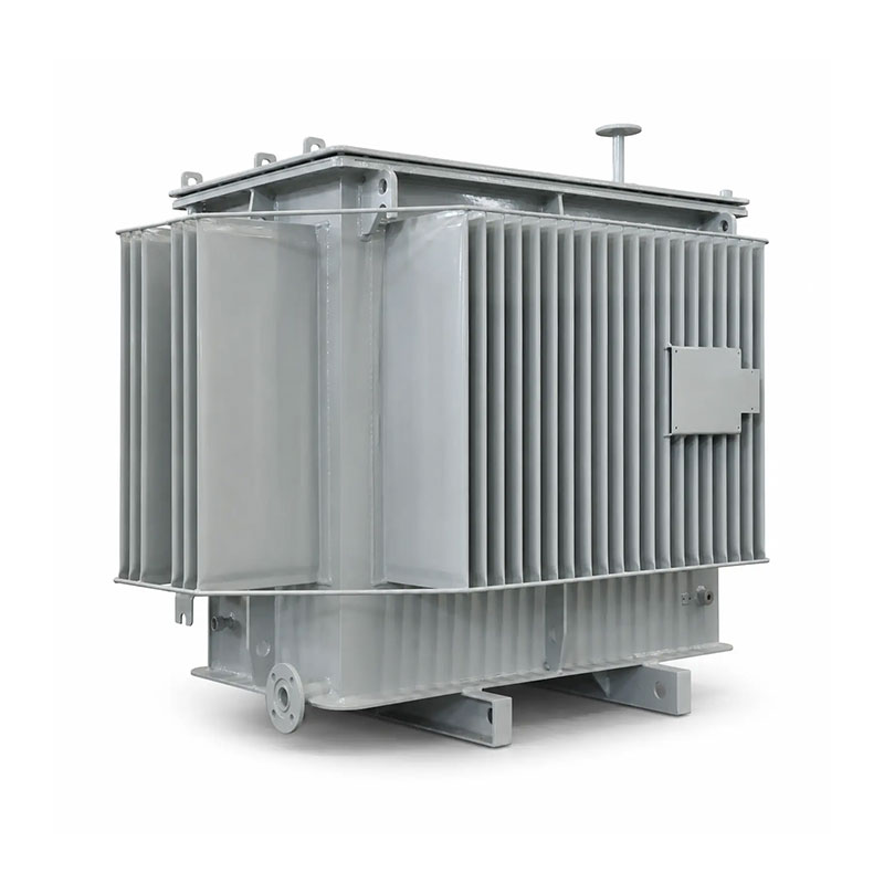
A corrugated tank performs several functions at once. It contains transformer oil, encloses the active part, provides part of the cooling surface, and may contribute to volume compensation in a hermetically sealed transformer.
Prennox’s current Corrugated Transformer Tanks page describes the corrugated wall as both an enclosure and a cooling surface and states that tanks are built to approved drawings. The same page lists configurable corrugation pitch, depth, panel width, tank dimensions, material thickness, and coating system.
This means transformer tank corrugation design should not be optimized as an isolated sheet-metal feature. The corrugation geometry needs to match the transformer’s heat losses, oil volume, temperature-rise target, pressure or vacuum requirements, active-part clearances, transport envelope, and fabrication process.
Start With the Transformer Thermal Duty
Corrugations increase the external surface area available for heat transfer, but the required area depends on the transformer’s actual losses and operating conditions.
IEC 60076-2 applies to liquid-immersed transformers, identifies cooling methods, defines temperature-rise limits, and gives methods for temperature-rise testing. This is important because the final thermal performance is a transformer-level requirement, not a geometric property of the tank alone.
For transformer tank corrugation design, the engineering team should therefore know the expected no-load and load losses, cooling method, ambient conditions, oil temperature assumptions, and target temperature rise before final corrugation dimensions are frozen.
A deeper corrugation can increase area, but that does not guarantee a proportional reduction in temperature rise. Effective oil circulation, air movement between fins, fin spacing, wall temperature, and the entire tank layout still influence heat rejection.
Corrugation Pitch Controls Spacing and Total Panel Geometry
Corrugation pitch is the repeating distance between adjacent corrugation features. It affects the number of fins that can fit into a given wall length and changes both cooling area and the open space available for natural air movement.
Prennox currently publishes a corrugation-pitch manufacturing range of 40–60 mm. This is a production range, not a universal recommendation for every transformer.
In transformer tank corrugation design, reducing pitch can increase the number of corrugations over a fixed length, but closer spacing can also restrict free air movement and make coating or cleaning more difficult. Increasing pitch creates wider air channels but reduces the number of corrugations within the same panel length.
The correct pitch should therefore be selected together with fin depth, panel height, transformer losses, natural-convection conditions, and available tank length.
Corrugation Depth Changes Cooling Area and Tank Envelope
Corrugation depth is one of the most influential geometric parameters because it changes how far the corrugated wall projects outward from the tank body.
Prennox currently lists a corrugation-depth manufacturing range of 30–400 mm. Again, this should be interpreted as a manufacturable range rather than a thermal design recommendation.
A deeper fin can increase external surface area and may improve the tank’s ability to accommodate oil-volume change in some sealed-tank designs. However, deeper corrugations also increase transformer width, alter mechanical flexibility, create longer formed surfaces, and can affect transport clearances.
For this reason, transformer tank corrugation design should not use maximum fin depth as a default. The designer should balance cooling area, oil expansion, structural behavior, tank envelope, coating access, and manufacturing stability.
| Corrugation parameter | Main design effect | Risk if selected in isolation |
|---|---|---|
| Pitch | Controls spacing and number of fins | Airflow and coating access may be restricted |
| Depth | Changes surface area and tank projection | Transport width and deformation behavior can change |
| Panel width | Defines manufacturable corrugated section | Interfaces and welding zones may not fit the tank layout |
| Plate thickness | Affects stiffness, forming and mechanical strength | Too thin or too thick can create structural or fabrication issues |
| Number of corrugations | Changes total area and flexible-wall behavior | More fins do not automatically mean proportional cooling improvement |
Panel Width Must Match Both Manufacturing and Tank Layout
Corrugated panels are manufactured in finite widths. Prennox currently lists a panel-width range of 300–1,400 mm in 50 mm increments.
For transformer tank corrugation design, panel width should be coordinated with the flat zones needed for flanges, brackets, labels, grounding pads, valves, lifting structures, cable boxes, and other interfaces.
A tank side wall may not be corrugated from edge to edge. The design can require flat sections near corners, top and bottom weld zones, mounting points, or accessory interfaces.
The drawing should therefore show where the corrugated panel begins and ends, rather than simply giving a total wall width and a general note that says “corrugated.”
Plate Thickness Influences Forming, Stiffness and Flexibility
Corrugated walls need enough strength to remain oil-tight and stable, but they also need to be formable into the approved geometry.
Prennox states that material and thickness are supplied as specified. The correct value depends on tank size, corrugation depth, reinforcement, pressure or vacuum requirement, welding, oil mass, transport loads, and the complete mechanical design.
In transformer tank corrugation design, plate thickness should therefore be selected by structural review rather than copied from a transformer with similar kVA.
A thicker plate can increase stiffness but may require greater forming force and can reduce the flexibility of the corrugated wall. A thinner plate can be easier to form but may need more careful review of deformation, welding distortion, and pressure performance.
Sealed Transformers Need Oil-Volume Change to Be Considered
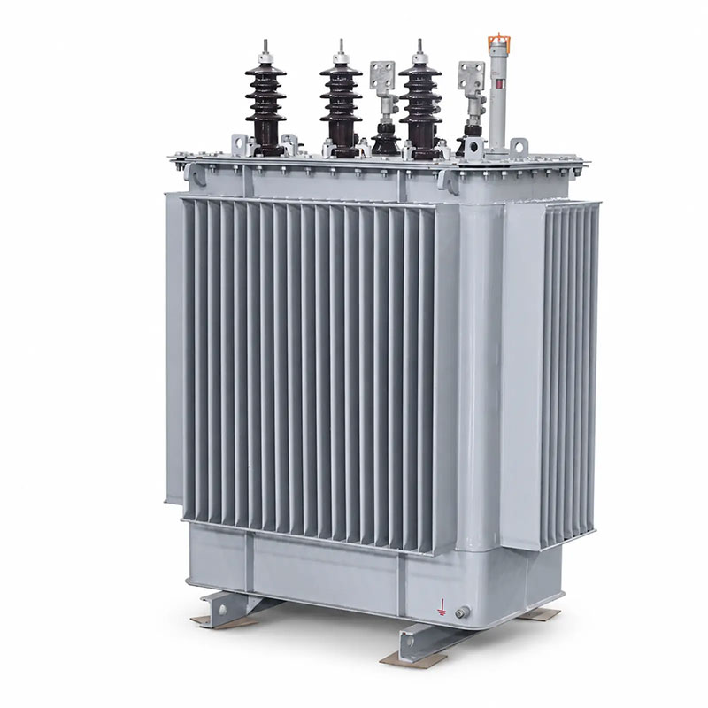
Transformer oil expands as temperature rises and contracts as it cools. In a hermetically sealed corrugated tank, the flexible corrugated walls can participate in accommodating this volume change.
This is one reason transformer tank corrugation design cannot be based only on cooling surface. The mechanical movement of the fins under oil-volume change also needs to remain within the approved stress and deformation range.
The required compensation depends on oil quantity, operating temperature range, free volume, tank geometry, corrugation flexibility, and the sealed-tank concept.
Designers should avoid using a generic “expansion per fin” value from another tank unless the same geometry, plate thickness, material, oil volume, and temperature range are confirmed.
Corrugation Geometry Affects Mechanical Flexibility
Corrugated steel behaves differently from a flat reinforced wall. The folds can increase flexibility in one direction while still providing structural shape and cooling area.
For sealed tanks, this flexibility can be useful for oil expansion. But the same flexibility means the wall must be checked for excessive deformation under internal pressure, vacuum filling, transport loads, and handling.
IEC 60076-1 includes general requirements related to transformer tanks, including pressure, vacuum, and leak testing. The exact test condition should come from the project specification and approved transformer design.
A sound transformer tank corrugation design therefore balances flexible movement with adequate mechanical strength.
Oil Circulation Still Matters Even With More Surface Area
Corrugated fins only reject heat effectively if hot transformer oil transfers heat to the tank wall.
Oil-side circulation depends on active-part geometry, internal tank clearances, oil paths, winding losses, temperature gradients, and the location of hot and cold oil regions.
This means transformer tank corrugation design cannot be validated by external area alone. A large corrugated surface may not perform as expected if the oil circulation near that wall is poor.
The transformer thermal model or validated design method should therefore connect the internal oil path to the external cooling surface.
Airflow Between Corrugations Needs Space
Natural-air cooling depends on buoyancy-driven air movement around the tank. Warm air rises along heated surfaces while cooler air replaces it from below.
If corrugations are too closely packed for the actual fin depth and installation layout, the air passages can become restrictive. Nearby walls, barriers, other transformers, or enclosures can also reduce natural airflow.
A practical transformer tank corrugation design should therefore consider not only the fin-to-fin spacing but also site clearances and the final transformer installation.
The same tank may cool differently in an open test area and inside a restricted enclosure or poorly ventilated substation.
Flat Interface Zones Should Be Planned Before Forming
Corrugations are not ideal locations for every accessory. Flanges, valves, grounding pads, brackets, lifting structures, nameplates, and cable-box interfaces often require flat, reinforced areas.
Before forming starts, the transformer tank corrugation design should reserve the required flat zones and define how corrugated panels transition into those regions.
If accessories are added after the corrugation layout is already fixed, the fabricator may need awkward reinforcement or rework that complicates welding and coating.
The earlier Transformer Tank Drawing Requirements guide explains how all interfaces should be located from controlled datums before fabrication.
Welding Layout Can Affect Corrugation Performance
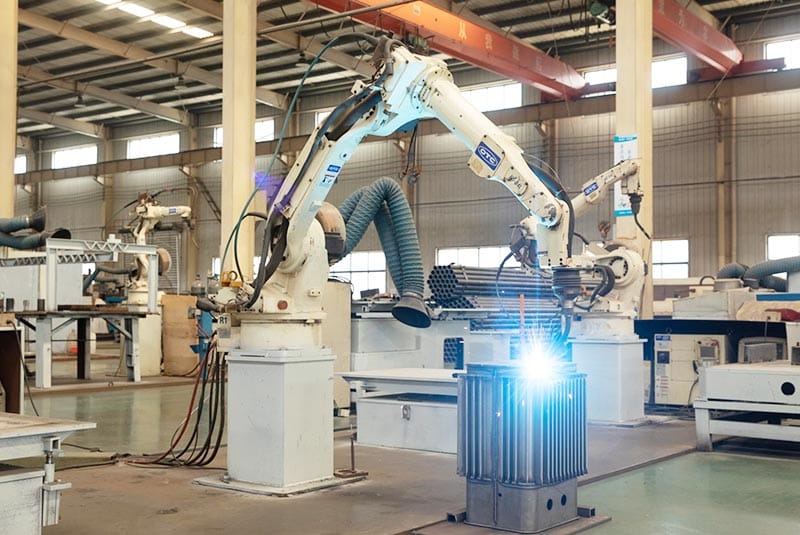
Corrugated panels need to be welded into the tank structure without excessive distortion or loss of oil tightness.
The design should identify top and bottom seam geometry, side transitions, corner joints, flat-to-corrugated interfaces, and any reinforcing welds required by the approved structure.
In transformer tank corrugation design, heat input and weld sequence matter because thin formed sheet can distort more easily than heavy flat plate.
Prennox states that controlled fabrication can include laser cutting, corrugation forming, and robotic welding where suitable. However, process automation does not replace the need for an approved weld design and dimensional inspection.
Leak Testing Must Match the Tank Design
Every corrugated tank contains many formed surfaces and welded seams, so leak testing is an essential acceptance step.
Prennox states that leak-test method, pressure, and holding time are confirmed during technical review. This is preferable to applying one universal pressure to every transformer tank corrugation design.
The project specification should state the required pressure or vacuum condition, holding time, acceptance method, and whether the test applies to the tank body, cover assembly, or complete transformer tank system.
The test requirement should be known before plate thickness, reinforcement, and welding details are finalized.
Coating Access Should Be Considered in Fin Geometry
Corrugated walls create narrow channels, fold lines, edges, and welded transition zones that can be harder to prepare and coat than a flat panel.
Deep fins and small pitch can make access more difficult for blasting, phosphating, painting, inspection, and touch-up.
A complete transformer tank corrugation design should therefore consider the coating process as part of geometry selection. The project coating specification should define pretreatment, paint system, color, dry-film requirements where applicable, and inspection method.
Designing very tight corrugations without considering coating access can produce a tank that meets drawing dimensions but is difficult to protect consistently against corrosion.
Transport Width Can Limit Corrugation Depth
Corrugated walls project beyond the nominal flat tank body. That projection contributes directly to shipping width.
A transformer designed with deep corrugations may satisfy thermal requirements yet exceed a transport route, truck, container, door opening, or site-access restriction.
For this reason, transformer tank corrugation design should be checked against both installed and shipping envelopes before the tank drawing is released.
If transport becomes the limiting factor, the project may need to revise tank geometry or consider a different cooling architecture, such as a flatter tank with detachable radiators. The earlier Corrugated Transformer Tank vs Radiator Cooling guide covers that system-level comparison.
Dimensional Tolerances Should Be Assigned to Functional Features
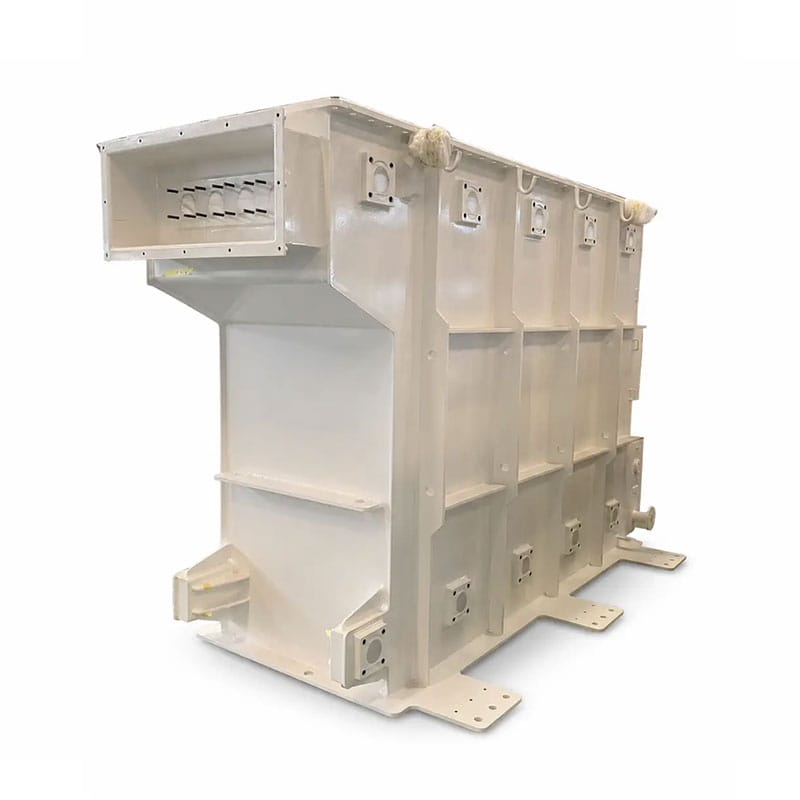
Corrugated geometry has multiple dimensions that can vary during forming: pitch, depth, panel width, flat transition width, overall wall length, and final tank dimensions.
A good transformer tank corrugation design should identify which dimensions are function-critical and which are general manufacturing dimensions.
For example, flange positions, cover fit, overall shipping envelope, base dimensions, and mating interfaces may need tighter tolerance than individual corrugation depth if the thermal design allows a defined range.
The inspection plan should match the drawing so that the fabricator and buyer measure the same features using the same datums.
Common Transformer Tank Corrugation Design Mistakes
Maximizing Fin Depth Without Checking Transport
Deeper corrugations can increase surface area, but they also increase tank width and change mechanical behavior.
Using the Smallest Pitch to Fit More Fins
More corrugations do not automatically produce proportional cooling. Airflow, fin depth, coating access, and manufacturing stability also matter.
Ignoring Oil-Volume Compensation in Sealed Designs
In a hermetically sealed transformer, the corrugated wall can participate in oil-expansion compensation, so mechanical flexibility needs to be included in the design.
Copying Plate Thickness From a Similar Transformer
Plate thickness should be reviewed against the actual dimensions, corrugation depth, pressure/vacuum conditions, welding, transport, and oil mass.
Leaving Leak-Test Conditions Until After Fabrication
The required test can influence structure and weld design. It belongs in the specification before production.
What to Include in a Transformer Tank Corrugation Design RFQ
A useful transformer tank corrugation design RFQ should provide both the tank drawing and the engineering context.
Transformer data: application, transformer rating, oil quantity or tank-volume basis where relevant, expected losses, cooling method, and installation conditions.
Tank geometry: overall length, width, height, corrugated-wall locations, flat interface zones, cover design, and active-part clearances.
Corrugation geometry: pitch, depth, panel width, panel height, number of corrugations, transition details, and any sealed-tank flexibility requirement.
Material: steel grade, plate thickness, reinforcement, and any special forming requirement.
Interfaces: openings, flanges, valves, grounding pads, lifting points, radiator or accessory connections.
Inspection: dimensional tolerances, welding requirements, pressure/vacuum or leak-test method, coating system, and required reports.
What Prennox Needs Before Reviewing a Corrugated Tank Project
Prennox currently asks buyers to provide the tank drawing and overall dimensions, corrugation dimensions and layout, material grade and plate thickness, cover and sealing requirements, openings and flange details, leak-test requirements, coating specification, quantity, and destination.
The current published manufacturing ranges are 40–60 mm corrugation pitch, 30–400 mm corrugation depth, and 300–1,400 mm corrugated panel width in 50 mm increments. These values describe manufacturing capability; they do not determine the correct transformer tank corrugation design for a specific transformer.
For drawing preparation, review the Transformer Tank Drawing Requirements guide. For thermal architecture, the Corrugated Transformer Tank vs Radiator Cooling article can help before the cooling concept is frozen. Project drawings can be sent through the Contact page.
Conclusion
Transformer tank corrugation design is a combined thermal, mechanical, and manufacturing decision. Pitch, depth, panel width, plate thickness, oil-volume compensation, cooling area, airflow, welding, pressure behavior, leak testing, coating, and transport all interact.
The correct design is not the one with the deepest fins or the highest number of corrugations. It is the one that gives the transformer enough validated cooling and mechanical margin while remaining manufacturable, testable, transportable, and compatible with the approved tank interfaces.
When these inputs are agreed before forming and welding, the corrugated tank can be designed as an integrated transformer component rather than as a generic sheet-metal enclosure.
FAQ
What is transformer tank corrugation design?
Transformer tank corrugation design defines the pitch, depth, panel width, layout, material thickness, flexible-wall behavior, cooling area, interfaces, and manufacturing requirements of corrugated walls used on oil-immersed transformer tanks.
Does deeper corrugation always improve transformer cooling?
No. Greater depth can increase geometric surface area, but actual cooling also depends on oil circulation, air movement, pitch, installation clearances, wall temperature, transformer losses, and the complete thermal design.
What corrugation pitch should be used for a transformer tank?
The correct pitch depends on cooling, geometry, manufacturing, and airflow requirements. Prennox currently publishes a manufacturable range of 40–60 mm, but the project-specific value should come from the approved design.
Why does plate thickness matter in a corrugated transformer tank?
Plate thickness affects forming, stiffness, flexible-wall behavior, welding distortion, pressure/vacuum performance, and transport strength. It should be selected from the actual tank design rather than transformer capacity alone.
What information should be included in a transformer tank corrugation design RFQ?
Provide the tank drawing, overall dimensions, corrugation pitch, depth, panel width and layout, material and thickness, cooling and sealed-tank requirements, openings and flanges, pressure/leak tests, coating, quantity, and destination.