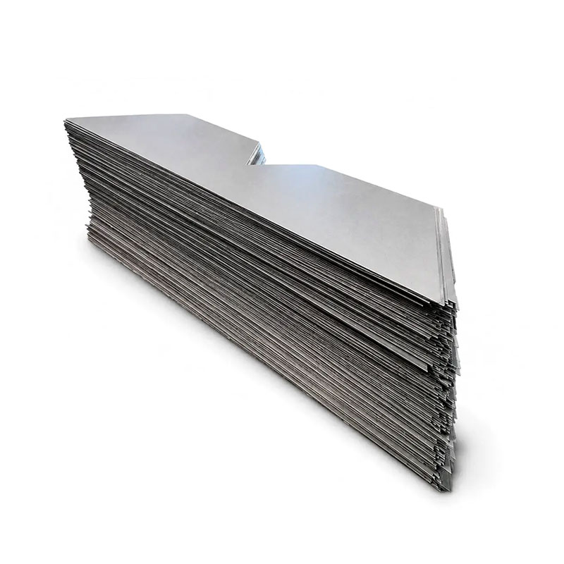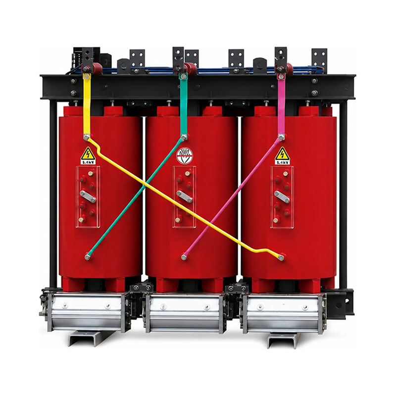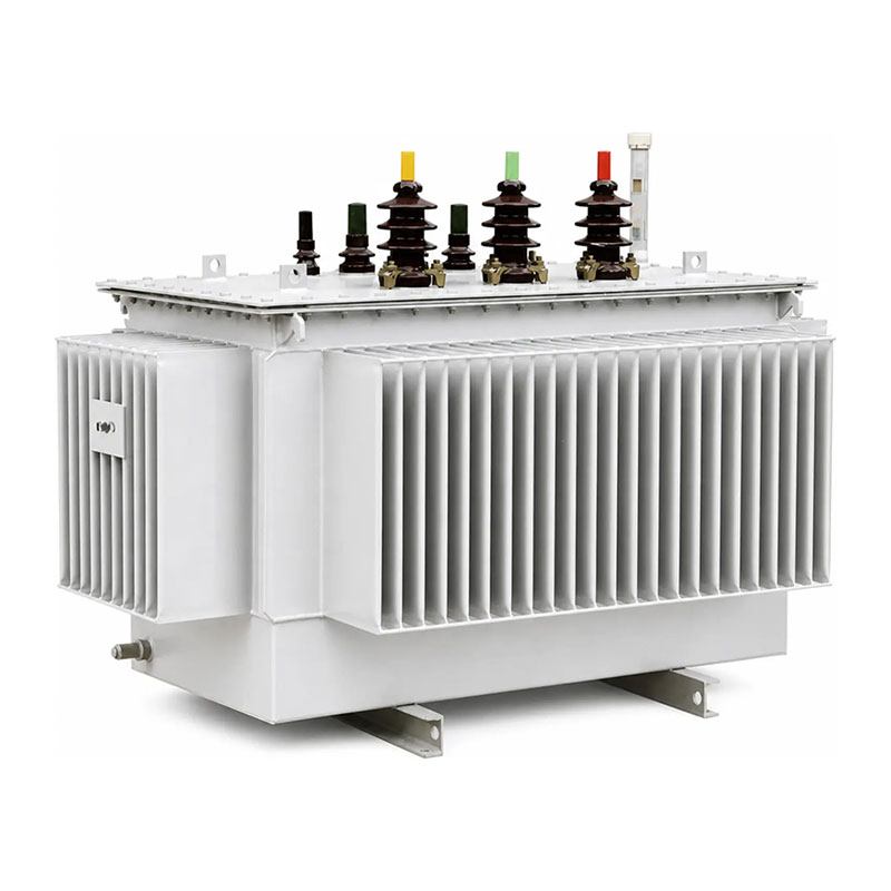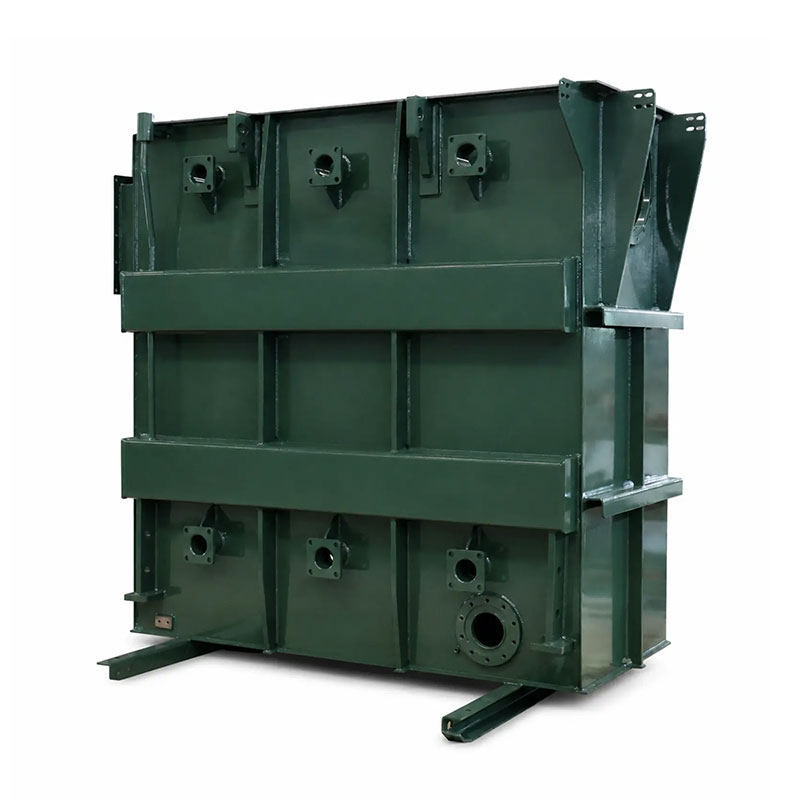
A transformer tank drawing is the manufacturing reference that turns a transformer layout into a weldable, testable, and installable oil-filled enclosure. If the drawing only shows overall length, width, and height, the fabricator may still be missing the information needed to position bushings, radiators, valves, lifting points, grounding pads, wheels, stiffeners, covers, cable boxes, conservator connections, and other project-specific interfaces.
For oil-immersed transformer projects, the tank drawing also controls more than fit. It affects oil volume, active-part clearance, cooling arrangement, transport dimensions, pressure and vacuum behavior, leak tightness, coating access, site assembly, and maintenance. This is why the tank should not move into cutting and welding until the mechanical drawing and inspection requirements are fully approved.
This guide explains how to prepare a practical transformer tank drawing before fabrication. It covers general dimensions, plate thickness, corrugated or reinforced structures, openings, flanges, radiator connections, lifting and base details, welding, tolerances, leak testing, coating, drawing revision control, and the RFQ information a tank supplier needs before production.
Why a Transformer Tank Drawing Must Be a Fabrication Document
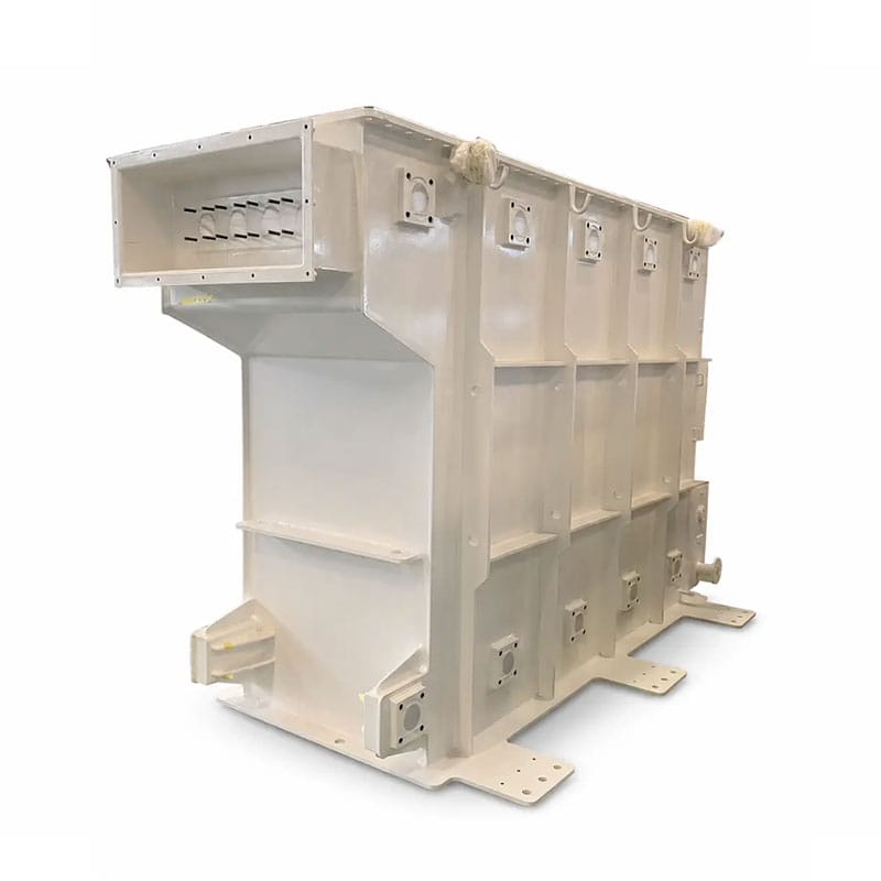
A transformer general arrangement drawing and a tank fabrication drawing are related, but they are not always the same document. The general arrangement shows how the transformer fits together as a complete product. The fabrication drawing must give the tank manufacturer enough detail to cut, form, weld, machine, inspect, coat, and pack the actual steel structure.
Prennox currently states that both its Thùng Biến Áp Tôn và Xe tăng biến áp tùy chỉnh are built to approved drawings. The corrugated version is configured around tank dimensions, corrugation geometry, interfaces, material thickness, cover, leak-test requirements, and coating. The custom welded version adds project-specific reinforcement, lifting points, base supports, cooling connections, and other non-standard interfaces.
This makes the transformer tank drawing the common reference between transformer design, purchasing, fabrication, quality control, coating, logistics, and final assembly. If those teams work from different revisions or incomplete information, even a dimensionally accurate tank can still fail the project.
Overall Dimensions Should Reflect the Finished Tank Envelope
The drawing should clearly identify the finished tank length, width, and height and define whether those values include corrugations, radiator flanges, mounting brackets, lifting lugs, wheels, cable boxes, covers, or other projections.
Một hữu ích transformer tank drawing separates the main tank-body dimensions from the total shipping and installation envelope. This matters because a transformer can fit the foundation but still exceed a door opening, truck width, container height, or crane clearance once external accessories are installed.
Where transport restrictions are critical, the drawing package should show the transport configuration separately from the final assembled configuration. Detachable radiators, removable conservators, removable wheels, or separately packed bushings can materially change shipping dimensions.
Use Clear Datums for All Interface Dimensions
Openings and brackets should not be located by chained dimensions that accumulate tolerance across the tank. Instead, the transformer tank drawing should use clear datums such as tank centerlines, finished flange faces, cover edges, or base reference planes.
This makes production inspection easier and reduces the risk that one early dimensional deviation shifts every downstream interface.
Material Grade and Plate Thickness Must Be Defined by Component
The tank body, cover, base, stiffeners, corrugated panels, brackets, flanges, and lifting parts do not necessarily use the same plate thickness. The drawing or linked bill of materials should identify material grade and thickness for each structural part.
Prennox’s current product pages state that transformer tank material and plate thickness are supplied as specified. This is the correct boundary: the manufacturer should not infer plate thickness from transformer capacity alone.
Trong một transformer tank drawing, plate thickness should be coordinated with tank dimensions, reinforcement, corrugation geometry, pressure or vacuum requirements, welding distortion, transport loads, lifting, and the overall mechanical design. Increasing thickness can improve stiffness, but it also changes weight, forming requirements, weld heat input, and cost. The correct value comes from the approved structural design.
Corrugated Tanks Need a Dedicated Fin-Wall Detail
A corrugated transformer tank combines the oil enclosure with part of the cooling surface. The corrugations also affect mechanical flexibility, oil-volume compensation, overall tank width, welding length, coating access, and fabrication tooling.
For this reason, a corrugated transformer tank drawing should state more than “corrugated side wall.” Prennox currently publishes a configurable corrugation pitch of 40–60 mm, corrugation depth of 30–400 mm, and corrugated panel width of 300–1,400 mm in 50 mm increments. These are published manufacturing ranges, not project recommendations. citeturn129663search0
The approved drawing should identify corrugation pitch, fin depth, panel width, number of corrugations, start and end positions, top and bottom geometry, welded borders, transition areas, and any flat zones reserved for labels, brackets, valves, grounding pads, or electrical interfaces.
If the corrugated wall is also part of a hermetically sealed transformer concept, the design should be coordinated with the expected oil-volume change and tank mechanical behavior. The product structure should not be copied from another transformer simply because both designs have similar kVA ratings.
Reinforced Welded Tanks Need Stiffener and Support Details
Custom welded tanks often use flat or formed steel panels together with reinforcement ribs, channels, brackets, or structural frames. Prennox states that its custom tanks can use project-specific reinforcement and non-standard interfaces based on the approved design. citeturn129663search2
A reinforced transformer tank drawing should identify the stiffener profile, length, orientation, spacing, end treatment, and weld arrangement. It should also show whether the stiffener is internal or external and whether it interferes with radiators, cable boxes, valves, labels, lifting points, or coating access.
The drawing should also define base supports and skid structures. These parts transfer tank and active-part loads to the foundation and can be important during lifting, jacking, transport, and installation.
Openings, Flanges and Nozzles Must Be Fully Defined
Tank fabrication frequently becomes difficult when the general arrangement shows that an accessory exists but does not define the actual interface. A flange location without flange thickness, bolt pattern, hole size, sealing face, and nozzle diameter is not enough for fabrication.
Một hoàn chỉnh transformer tank drawing should identify every opening that belongs to the tank scope. Depending on the transformer design, this may include radiator connections, conservator pipes, drain and filter valves, sampling valves, pressure-relief-device openings, thermometer pockets, level gauges, bushings, cable boxes, inspection covers, vacuum filling connections, and earthing pads.
Each interface should show orientation and reference position. For circular flanges, bolt-circle diameter, number and size of holes, hole orientation, gasket surface, flange thickness, and nozzle projection should be defined. For rectangular interfaces, all hole coordinates and sealing dimensions should be clear.
| Interface item | Drawing information to define | Typical risk if omitted |
|---|---|---|
| Radiator connection | Center position, flange size, bolt pattern, nozzle size and orientation | Radiator does not align with the tank |
| Valve opening | Nominal size, thread/flange type, elevation and access direction | Valve cannot be installed or operated |
| Bushing / cable box interface | Cutout, bolt pattern, support detail and orientation | Electrical interface conflicts with the enclosure |
| Inspection opening | Clear opening, cover plate, gasket and bolt pattern | Maintenance access is insufficient |
| Grounding pad | Position, plate size, hole/thread details | Site grounding cannot be connected as planned |
Radiator Connections Must Match the Cooling Design
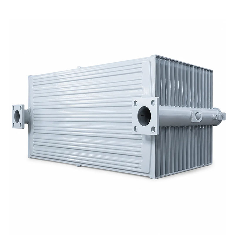
Radiator positions are not just mechanical features. Their elevation and connection geometry also influence oil circulation. The transformer tank drawing should therefore be coordinated with the approved radiator and thermal design.
If detachable radiators are used, flange faces and center distances need to match the corresponding radiator drawing. Prennox’s Bộ tản nhiệt biến áp có thể tháo rời loại PC page uses drawing-based flange and connection data for this reason.
If a fixed radiator is used, the welding or connection arrangement should be clearly defined. If the tank uses corrugated walls instead of external radiators, the fin-wall dimensions must reflect the validated cooling design rather than simply maximizing corrugation depth.
Trước đó Corrugated Transformer Tank vs Radiator Cooling guide explains why cooling architecture should be decided before the tank interface drawing is frozen.
Lifting, Jacking and Transport Details Need Structural Review
A transformer tank may be lifted as an empty fabrication, as a tank with active part, or as a fully assembled transformer. These are very different load cases.
Các transformer tank drawing should therefore identify the intended lifting condition and show lifting lugs, jacking pads, pulling eyes, skid or wheel arrangements, and center-of-gravity information where required by the project. Lifting points should not be placed only where they are convenient to weld.
The supplier should also know whether transport tie-down points or special support frames are required, and the transformer tank drawing should identify them. If accessories are removed for shipment, the transport drawing should identify blanking plates, protective covers, and temporary braces.
Cover, Gasket and Sealing Details Should Be Included Before Fabrication
Some transformer tanks are supplied with covers; others are supplied as tank bodies only. Prennox’s corrugated tank page explicitly lists both supply configurations. citeturn129663search0
If the cover is included, the transformer tank drawing should define cover plate thickness, flange width, bolt spacing, stiffeners, openings, lifting points, gasket groove or sealing face, and the method used to control deformation during welding.
The buyer should also define the gasket system or at least the interface dimensions required by the approved gasket. Sealing-surface flatness and weld distortion can directly affect leak tightness, so they should be part of the drawing and inspection plan rather than left until assembly.
Welding Requirements Must Be Tied to Joint Type and Inspection
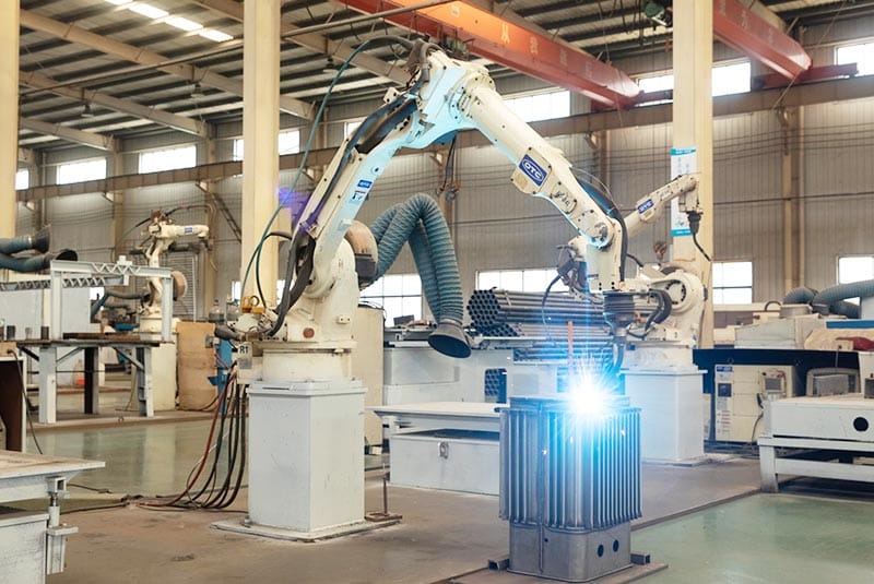
Transformer tanks contain many welded seams, and different joints may use different welding preparations and inspection requirements. The drawing should identify weld type where necessary and reference the approved welding specification.
Một thực tế transformer tank drawing package should clarify continuous versus intermittent welds, full-penetration requirements where applicable, fillet-weld size where controlled, sealing welds, joints requiring grinding, and areas where weld spatter or sharp projections are unacceptable.
Prennox states that robotic welding can be used where suitable, but the welding method does not remove the need for approved joint design and inspection. citeturn129663search2
Dimensional inspection and leak testing should be coordinated with welding because heat distortion can move flanges and openings after tack-up. Critical interfaces on the transformer tank drawing should be checked after final welding, not only before it.
Pressure, Vacuum and Leak Tests Must Be Specified Explicitly
IEC 60076-1:2011 includes requirements covering liquid-preservation systems and vacuum, pressure, and leak tests on transformer tanks. citeturn149544search0 The exact test that applies to a project depends on transformer type, tank design, purchaser specification, and agreed standard.
Điều này có nghĩa là a transformer tank drawing should either state or reference the required pressure, vacuum, leak-test method, holding time, and acceptance criteria. A note that says only “tank must not leak” is not an adequate inspection specification.
Prennox’s current corrugated tank page states that leak-test method, pressure, and holding time are confirmed during technical review, while its custom tank page states that leak testing follows the agreed inspection plan. citeturn129663search0turn129663search2
For sealed tanks, the test basis may differ from a conservator-type tank. If the tank must withstand vacuum filling, that requirement should be confirmed before material thickness and reinforcement are frozen.
Coating Requirements Should Be Defined Before Steel Is Cut
Surface preparation and coating are often treated as final-stage tasks, but the tank geometry can make some surfaces difficult to blast, inspect, or paint. Narrow gaps, overlapping brackets, deep corrugations, sharp edges, and inaccessible welds can all affect coating quality.
ISO 12944-4:2017 covers types of steel surface and surface preparation for protective paint systems and remains current while a replacement edition is under development. citeturn129663search8
Một hoàn chỉnh transformer tank drawing package should identify the project coating specification, color if required, surface-preparation standard, areas that remain uncoated, masking requirements, internal coating if applicable, and inspection method. If dry-film thickness is contractually controlled, the drawing or coating specification should define how inaccessible or complex areas are handled.
Do not wait until fabrication is complete to discover that a bracket blocks access to a surface that must be coated and inspected.
Dimensional Tolerances Should Follow Function
Not every tank dimension needs the same tolerance. Critical interfaces such as radiator flanges, cover sealing faces, bushing openings, wheel centers, busduct interfaces, and base mounting points may require tighter control than nonfunctional external panels.
A good transformer tank drawing separates functional tolerances from general fabrication tolerances. It should also state whether dimensions are measured before or after coating and whether the tank is free-standing, clamped, or supported in a defined condition during inspection.
This prevents unnecessary over-tolerancing while protecting the dimensions that actually affect transformer assembly.
Drawing Revision Control Is Essential Before Cutting Begins
Tank drawings often change late in transformer design because of bushing positions, radiator layout, cable-box dimensions, conservator piping, active-part clearance, or customer comments. If a supplier starts laser cutting from an old revision, the error can affect dozens of welded parts.
Mỗi transformer tank drawing should therefore have a controlled drawing number, revision, approval status, and release date. The purchase order and manufacturing release should reference the same revision.
When a revision changes an interface, the buyer should identify whether already-cut plates or welded subassemblies can still be used. Sending a revised PDF with the same filename but no formal revision status creates avoidable production risk.
Inspection Drawings Should Identify Critical Checkpoints
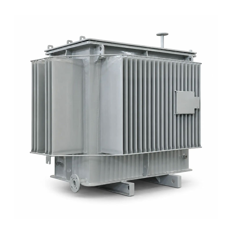
Before shipment, the tank should be checked against the approved drawing and inspection plan. Prennox’s tank pages state that key dimensions, interface positions, welded areas, and leak testing are checked against approved documentation. citeturn129663search0turn129663search2
A useful inspection sheet can extract the critical values from the transformer tank drawing: overall dimensions, flange centerlines, mounting points, cover flatness, base dimensions, corrugation geometry, lifting-lug position, coating condition, leak-test result, and final identification.
| Inspection stage | Typical checks | Why the stage matters |
|---|---|---|
| Incoming steel | Material grade, thickness and traceability | Confirms the approved material basis |
| After cutting/forming | Plate dimensions, corrugations, holes and flange parts | Finds errors before welding adds more value |
| After tack-up | Datums, diagonals, interface location and fit-up | Allows correction before final welding |
| After final welding | Overall dimensions, flange positions, deformation and weld condition | Confirms the finished steel structure |
| Leak/pressure test | Specified test condition and acceptance | Verifies tank tightness and agreed mechanical requirement |
| After coating | Appearance, coating inspection, masking and final identification | Confirms shipment-ready condition |
Common Transformer Tank Drawing Mistakes
Showing Only the Transformer General Arrangement
A general arrangement may not contain weld details, plate thicknesses, flange dimensions, stiffeners, tolerances, or the inspection information required for tank fabrication.
Leaving Radiator Interfaces as “By Supplier”
If the radiator and tank are supplied by different companies, undefined flanges create a high risk of fit-up problems. The transformer tank drawing should define the mating interface.
Specifying Corrugations Without Pitch and Depth
“Corrugated wall” is not a fabrication dimension. Pitch, depth, panel width, count, start/end position, and flat interface zones should be shown.
Adding Leak-Test Requirements After Welding Is Complete
Pressure or vacuum requirements can influence plate thickness, reinforcement, weld design, and inspection planning. They should be defined before fabrication.
Using One Coating Note for Every Environment
Coating should reflect the project environment and approved paint system. Surface preparation, dry-film requirements, color, inspection, and repair rules may vary.
What to Include in a Transformer Tank Drawing RFQ
Một RFQ mạnh mẽ kết hợp bản vẽ với một lịch trình kỹ thuật ngắn. ở mức tối thiểu, cung cấp các transformer tank drawing, transformer type, overall dimensions, material grade, plate thickness, tank construction, cover requirement, reinforcement, openings, flanges, radiator or cooling interfaces, lifting details, base or wheel arrangement, working-pressure or vacuum requirements, leak-test requirements, coating specification, quantity, and destination.
For corrugated tanks, also provide corrugation pitch, depth, panel width, layout, and any sealed-tank design information that affects the flexible walls.
For non-standard welded tanks, add reinforcement details, structural supports, special interfaces, and any customer-specific welding or inspection requirements.
If the supplier is expected to complete any mechanical design rather than manufacture strictly to the drawing, that responsibility should be identified clearly before quotation.
What Prennox Needs Before Reviewing a Transformer Tank Drawing
For a corrugated tank, Prennox asks for the tank drawing and overall dimensions, corrugation dimensions and layout, material grade and plate thickness, cover and sealing requirements, openings and flanges, leak-test requirements, coating specification, quantity, and destination. citeturn129663search0
For a custom welded tank, Prennox additionally requests overall tolerances, reinforcement requirements, working-pressure or vacuum requirements, welding and inspection requirements, and the full interface details for the transformer assembly. citeturn129663search2
If the cooling concept is still being decided, review the Corrugated Transformer Tank vs Radiator Cooling article before freezing the tank drawing. If the project uses a standard corrugated construction, the existing Hướng dẫn bể biến áp sóng provides additional background.
Project drawings and technical schedules can be submitted through the Trang liên h for review before quotation.
Kết luận
Một hoàn chỉnh transformer tank drawing is not just an outline of a steel box. It is the controlled manufacturing document that defines dimensions, materials, plate thickness, corrugations or reinforcement, openings, flanges, cooling interfaces, lifting details, base supports, welding, leak tests, coating, tolerances, and the exact supply boundary.
The most important rule is to freeze the mechanical and inspection requirements before cutting and welding begin. Late changes to flange locations, pressure requirements, corrugation geometry, or coating access can create expensive rework even when the supplier follows the previous drawing correctly.
When the drawing, inspection plan, and purchase order all reference the same approved revision, tank fabrication becomes easier to quote, easier to inspect, and far less likely to create assembly problems at the transformer factory.
Câu hỏi thường gặp
What should a transformer tank drawing include?
A transformer tank drawing should include overall dimensions, material grade, plate thickness, tank construction, cover, reinforcement or corrugations, openings, flanges, cooling interfaces, lifting points, base or wheel details, welding requirements, tolerances, leak or pressure tests, coating, and drawing revision.
What extra information is needed for a corrugated transformer tank?
Specify corrugation pitch, depth, panel width, panel layout, start and end positions, flat interface areas, material thickness, and the sealed-tank or cooling requirements that affect the corrugated walls.
Should leak-test pressure be shown on the transformer tank drawing?
Yes, either directly or through a referenced inspection specification. The required test method, pressure or vacuum condition, holding time, and acceptance criteria should be agreed before fabrication.
Why must radiator flange positions be controlled carefully?
Radiator connections must match both the physical radiator and the transformer cooling layout. Incorrect elevation, center distance, bolt pattern, or orientation can prevent assembly and can also affect the intended oil-circulation path.
Can a transformer tank be fabricated from a general arrangement drawing only?
Sometimes a general arrangement contains enough detail, but often it does not. A fabrication-ready transformer tank drawing should provide plate, weld, interface, reinforcement, tolerance, inspection, and coating information in addition to the transformer envelope.