Transformer radiator sizing is often treated as a simple dimensional exercise: choose a panel width, select a center distance, add enough elements, and assume the cooling duty is covered. In practice, that approach can create costly design gaps. A radiator is only one part of the transformer thermal system, and its dimensions cannot be selected safely without understanding transformer losses, oil circulation, temperature-rise requirements, ambient conditions, radiator position, and the final cooling method.
For buyers, transformer manufacturers, and project engineers, the important distinction is between a radiator that is physically manufacturable and a radiator that is thermally suitable for a specific transformer. A supplier may be able to produce multiple panel widths, center distances, panel pitches, and panel quantities, but those manufacturing ranges do not automatically determine the heat dissipation required for your project.
This guide explains how to approach transformer radiator sizing from a procurement and engineering perspective. It focuses on the inputs that should be confirmed before an RFQ, how dimensional parameters interact with thermal performance, which mistakes frequently appear in specifications, and what data should be shared with a radiator supplier before drawings are frozen.
Why Transformer Radiator Sizing Starts With Heat, Not Dimensions
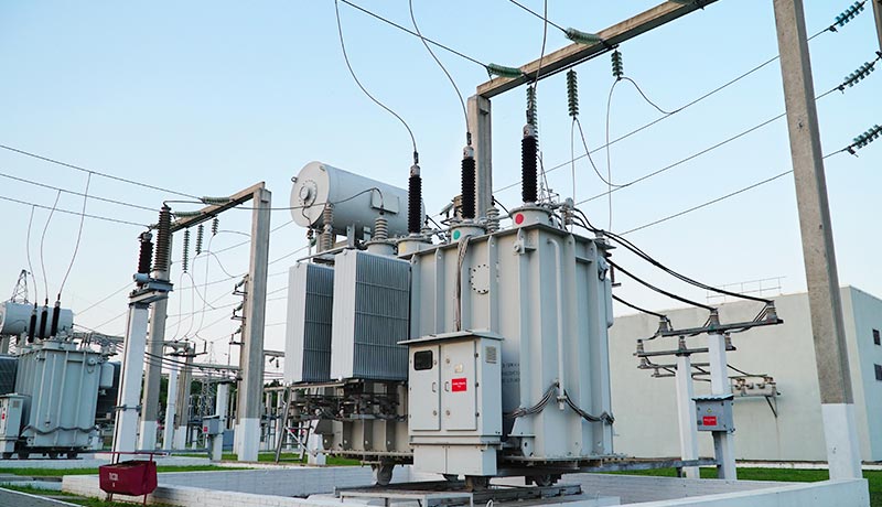
The fundamental purpose of a transformer radiator is to transfer heat from the insulating liquid to the surrounding air. Heat is generated mainly by transformer core and winding losses, then transported by oil to the cooling surfaces. The radiator does not create cooling capacity by itself; it provides a path for heat transfer as part of the complete transformer design.
That is why transformer radiator sizing should begin with the transformer thermal duty. The design team must know how much heat needs to be rejected under the relevant loading condition and what temperature-rise limits apply. The International Electrotechnical Commission addresses this in IEC 60076-2, which applies to liquid-immersed transformers, defines cooling methods, specifies temperature-rise limits, and provides temperature-rise test methods.
In other words, the required radiator arrangement must support the transformer’s thermal design basis. A radiator drawing with dimensions but no connection to total losses, ambient conditions, or temperature-rise requirements is incomplete from a thermal perspective.
Separate Manufacturing Range From Required Cooling Duty
One of the most common purchasing mistakes is to treat a supplier’s dimensional range as a sizing recommendation. These are different things.
For example, Prennox currently publishes the following manufacturing ranges for its PC Type Detachable Transformer Radiator and PG Type Fixed Transformer Radiator:
| Parameter | Published Manufacturing Range | What It Does Not Prove |
|---|---|---|
| Panel width | 480 / 520 mm | It does not by itself prove a specific heat-dissipation capacity. |
| Center distance | 500–4500 mm | It does not prove suitability for a particular transformer rating. |
| Panel pitch | 40 / 45 mm | It does not mean every pitch performs identically in every arrangement. |
| Number of panels | 5–35 | More panels do not automatically produce a proportional cooling increase. |
| Connection type | Fixed or detachable, depending on model | Connection style alone does not determine thermal performance. |
These dimensions are valuable because they tell the buyer what can be fabricated within the published product range. However, transformer radiator sizing still requires an engineering review to determine which geometry, quantity, and arrangement suit the transformer.
Calculate the Thermal Duty Before Choosing the Radiator
The first technical input for transformer radiator sizing is the heat load the cooling system must reject. At a minimum, the thermal assessment normally considers no-load loss, load loss at the specified condition, and any additional losses relevant to the transformer design.
Buyers should be careful when using transformer rated power as a shortcut. Two transformers with the same kVA or MVA rating can have different losses because of different core materials, conductor designs, impedance targets, winding geometries, loading conditions, or design margins. Their cooling requirements can therefore differ even when their nameplate ratings are similar.
A practical RFQ should identify the loss values that the transformer designer expects the cooling system to handle. If the radiator supplier is only manufacturing to a confirmed drawing, that drawing should already reflect the transformer designer’s thermal calculations. If the supplier is expected to participate in the thermal design, the loss data and thermal assumptions must be supplied explicitly.
Do Not Use Rated kVA as the Only Sizing Input
Rated capacity is useful context, but it is not enough for accurate transformer radiator sizing. A procurement request such as “radiator for a 1600 kVA transformer” leaves too many unknowns. The transformer could have different losses, cooling stages, ambient conditions, oil temperatures, or enclosure constraints.
A better transformer radiator sizing request includes the transformer rating together with no-load loss, load loss, cooling method, temperature-rise requirement, ambient conditions, radiator arrangement, and the applicable drawing.
Temperature Rise Defines the Real Design Target
The cooling system must maintain transformer temperatures within the specified limits under defined operating conditions. That makes temperature rise more important than radiator surface area alone.
IEC 60076-2 provides the main international framework for temperature rise in liquid-immersed transformers. It covers temperature-rise limits and test procedures, including winding hot-spot considerations. For a buyer, the practical lesson is straightforward: a radiator should not be accepted merely because its geometry looks larger than a previous design. The final transformer must still satisfy the required thermal limits.
In transformer radiator sizing, the temperature-rise target influences how much cooling surface and oil circulation are required. A design with tighter temperature limits may require more effective heat transfer than another transformer with similar losses but different thermal criteria.
It is therefore important to state the project’s temperature-rise requirements before radiator drawings are released for manufacturing.
Cooling Method Changes the Radiator Design Basis
Transformer radiators may be used in different cooling arrangements. Natural oil and natural air circulation operate differently from systems that use forced air or forced oil circulation. The radiator itself may look similar, but the system-level assumptions are not the same.
For natural cooling, oil circulation depends strongly on temperature differences, density differences, vertical arrangement, internal flow paths, connection geometry, and hydraulic resistance. With forced-air cooling, electric fans increase air movement across the radiator surface. IEC addresses fans used in transformer cooling circuits in IEC 60076-22-6.
Therefore, transformer radiator sizing should always identify the intended cooling designation and operating stages. A radiator designed for one cooling arrangement should not be assumed suitable for another simply because the physical connections fit.
ONAN and ONAF Should Not Be Treated as the Same Calculation
In a natural-air stage, heat transfer is limited by natural convection around the radiator surfaces. In a forced-air stage, fan position, airflow, radiator spacing, control logic, and operating sequence all influence performance. If a transformer has both natural and forced-air ratings, the radiator arrangement needs to support the required performance at each stage.
This is why transformer radiator sizing should record both the cooling method and the duty expected in each operating mode.
Panel Height and Center Distance Affect More Than Overall Size
Center distance is one of the most visible radiator dimensions. It usually relates to the vertical distance between connection centers or header positions, depending on the radiator design. Increasing the vertical dimension can affect available heat-transfer area and may also influence natural oil circulation because elevation contributes to the thermosiphon effect.
However, a larger center distance does not automatically guarantee better performance. The result also depends on oil-side pressure drop, radiator geometry, oil temperature, connection size, mounting elevation, and the relation between radiator and transformer active-part height.
IEC 60076-22-2, which covers removable radiators for liquid-immersed transformers, includes preferred dimensions and technical requirements relevant to interchangeability, operation, and testing. Buyers using detachable radiators should therefore treat center distance as both a mechanical interface dimension and a parameter within the larger transformer radiator sizing problem.
When preparing an RFQ, specify the required center distance from the approved transformer layout rather than selecting the maximum available value without engineering justification.
Panel Width, Pitch and Quantity Must Be Evaluated Together
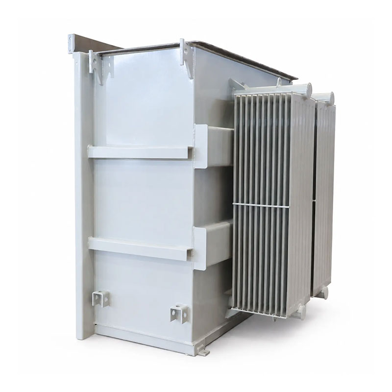
Radiator panel width, panel pitch, and the number of panels all affect the external geometry. They also influence how air moves between adjacent surfaces and how the radiator integrates with the transformer layout.
A frequent mistake in transformer radiator sizing is to assume that doubling panel quantity doubles useful cooling capacity. In practice, adjacent panels can interact thermally. Closely spaced surfaces can reduce free air movement, while additional elements change the total radiator depth and may affect installation clearances.
Similarly, changing panel pitch can influence air circulation and total radiator width. A compact arrangement may help with footprint restrictions, but the thermal effect should be evaluated using a validated calculation or design method rather than by geometry alone.
| Sizing Parameter | Mechanical Effect | Thermal Question to Check |
|---|---|---|
| Panel width | Changes radiator width and surface geometry | How does the selected width affect effective heat-transfer area? |
| Center distance | Controls vertical connection geometry | How does elevation affect oil circulation and heat dissipation? |
| Panel pitch | Changes spacing and overall depth | Is natural or forced airflow adequate between panels? |
| Panel quantity | Changes total radiator depth and mass | Does added surface remain thermally effective in the complete bank? |
| Number of radiator banks | Changes layout and tank connections | Is heat distributed effectively among all banks? |
The main lesson is that transformer radiator sizing should use a combination of dimensions, not a single panel count target.
Oil Circulation Can Limit an Otherwise Large Radiator
A radiator can only dissipate heat that reaches it. This makes oil circulation one of the most important and sometimes overlooked factors in transformer radiator sizing.
In naturally circulated systems, hot oil rises and flows toward the upper radiator connection. As the oil cools, it becomes denser and returns through the lower connection. The effectiveness of this process depends on the elevation difference, connection diameter, internal resistance, radiator geometry, oil viscosity, temperature difference, and transformer internal flow path.
If the connections are restrictive, poorly positioned, or incorrectly sized, simply adding more panels may not provide the expected improvement. The radiator may have sufficient theoretical surface area but insufficient oil flow through that surface.
For this reason, buyers should include connection details and radiator elevation in the drawing package. The supplier should not be expected to infer the transformer’s internal hydraulic design from panel dimensions alone. This is a core transformer radiator sizing check.
Radiator Position and Spacing Affect Air-Side Performance
The air around the radiator also needs space to move. A radiator mounted too close to another bank, a wall, a sound enclosure, a cable box, or another transformer may experience restricted airflow.
During transformer radiator sizing, the layout engineer should review the complete installation rather than the radiator drawing in isolation. Important checks include the spacing between adjacent radiator banks, clearance to the tank wall, clearance to barriers, fan position if forced air is used, and the direction of natural air movement around the transformer.
This is especially important for indoor transformers or outdoor transformers installed inside restricted compounds. A radiator performance assumption based on open-air conditions may not represent the actual installation if ventilation is poor.
Where the transformer is installed in a room, building ventilation may become part of the thermal design. The radiator removes heat from the oil, but the room still needs to reject that heat to the outside environment.
Fixed and Detachable Radiators Create Different Mechanical Requirements
Thermally, both fixed and detachable transformer radiators can provide cooling surface. Mechanically, however, they create different requirements.
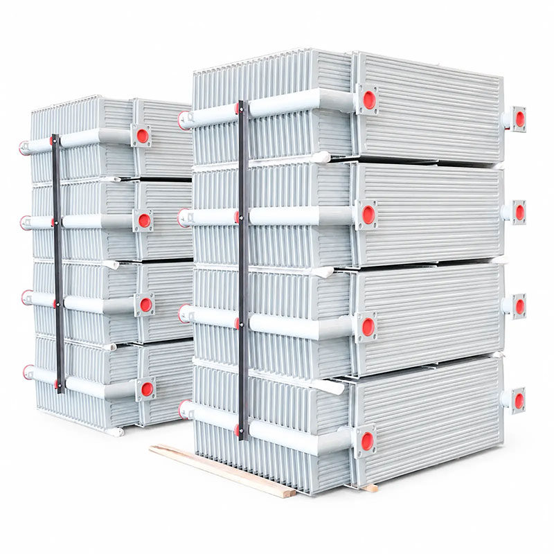
The PC detachable radiator uses flange connections and can be removed when required for transport, installation, or maintenance. This can be useful when the transformer shipping envelope is restricted or when the project wants replaceable cooling assemblies.
The PG fixed radiator is intended for permanent installation according to the transformer drawing. This may simplify the final assembly concept in projects where radiator removal is not required.
For transformer radiator sizing, the distinction matters because detachable arrangements introduce flange dimensions, sealing surfaces, gaskets, valves where specified, bolt patterns, and assembly tolerances. These features should be frozen together with the thermal design.
Do Not Ignore Pressure, Leak and Mechanical Test Requirements
Radiators are part of an oil-filled system, so thermal design cannot be separated from mechanical integrity. Welded seams, panel joints, headers, flange interfaces, and connections must remain oil-tight during production, transport, installation, and service.
IEC 60076-22-2 applies to radiators mounted on liquid-immersed power transformers and specifies service conditions, mechanical requirements, operating requirements, preferred dimensions, and type and routine tests for removable radiators.
A proper transformer radiator sizing RFQ should therefore include the required pressure or leak-test conditions, acceptance criteria, test records, flange details, and any special mechanical requirements. These details should not be added only after the radiator geometry has been approved.
How to Build a Better Transformer Radiator RFQ
A strong RFQ allows the supplier to understand both the manufacturing requirement and the engineering context. At minimum, the buyer should provide the following information for transformer radiator sizing and quotation review.
Transformer data: rated power, voltage class, cooling method, relevant loss values, temperature-rise requirements, insulating liquid, ambient conditions, installation altitude where applicable, and any special loading requirement.
Radiator geometry: panel width, center distance, panel pitch, panel quantity, number of radiator banks, connection location, installation orientation, and overall dimensional constraints.
Connection data: flange dimensions, bolt pattern, pipe or header size, sealing arrangement, valve requirements, and mating interfaces.
Manufacturing requirements: material specification, panel thickness if defined, welding requirements, internal cleanliness, oil flushing requirements, pressure or leak tests, surface pretreatment, coating, marking, and packing.
Project controls: approved drawing format, revision number, inspection documentation, quantity, shipping configuration, destination, and required technical records.
Providing these inputs makes transformer radiator sizing discussions more productive because the supplier can respond to a defined engineering basis rather than guessing from transformer capacity alone. A complete transformer radiator sizing package also reduces repeated drawing revisions during technical clarification.
Common Transformer Radiator Sizing Mistakes
Choosing the Maximum Available Panel Count
More elements increase geometric surface area, but that does not prove proportional thermal improvement. Airflow, oil circulation, panel spacing, and radiator-bank interaction still need to be checked.
Copying a Radiator From a Transformer With the Same Rating
Two transformers with the same rating may have different losses, thermal limits, winding designs, or installation environments. A previous radiator can be a reference, but it should not replace a new transformer radiator sizing review.
Ignoring the Difference Between Manufacturing Dimensions and Thermal Performance
A supplier’s published dimensions show what can be manufactured. They do not guarantee that every combination satisfies a particular transformer cooling duty.
Leaving the Connection Drawing Until Late in the Project
Connection location, flange geometry, and radiator elevation affect both fit and oil circulation. These details should be frozen before fabrication, not after radiator panels have already been produced.
Assuming Fan Addition Can Always Solve a Cooling Shortfall
Forced air may increase cooling performance, but fan-assisted operation changes the cooling method, control system, power supply, maintenance requirements, noise, redundancy strategy, and transformer rating basis. It should be engineered as part of the complete system.
What Prennox Needs Before Reviewing a Radiator Inquiry
For a practical quotation, send the radiator drawing or the key dimensional requirements, including panel width, center distance, panel pitch, panel quantity, connection details, surface-treatment requirements, and order quantity. If the radiator is detachable, include flange dimensions and mating details. If the project needs a fixed arrangement, provide the tank connection drawing and installation orientation.
If the thermal design is still being coordinated, include the transformer losses, cooling method, ambient conditions, required temperature rise, and expected radiator-bank arrangement so the technical discussion is based on the correct project context.
You can review the current Transformer Panel Radiators category, compare the PC Type Detachable Transformer Radiator with the PG Type Fixed Transformer Radiator, or use the Contact page to send a project drawing for review.
Conclusion
Transformer radiator sizing is not a matter of choosing the biggest available panel, the tallest center distance, or the highest element count. The correct radiator arrangement starts with the transformer’s heat losses, temperature-rise requirement, cooling method, oil circulation, ambient conditions, and installation layout.
Panel width, center distance, pitch, quantity, bank arrangement, and connection details should then be selected as part of the complete thermal and mechanical design. Finally, pressure testing, leak tightness, coating, transport configuration, and documentation need to be included in the purchase specification.
When buyers separate manufacturing range from required thermal performance, transformer radiator sizing quotations become easier to compare and the risk of late design changes is reduced. That makes transformer radiator sizing a disciplined engineering and procurement process rather than a catalogue selection exercise.
FAQ
How do you calculate transformer radiator sizing?
Start with transformer losses, required temperature rise, ambient conditions, cooling method, oil circulation, and installation layout. Then use a validated thermal design method to determine the required radiator arrangement and effective cooling surface. Panel dimensions alone are not enough.
Does adding more radiator panels always improve transformer cooling?
No. Additional panels increase geometric surface area, but actual performance also depends on oil flow, air circulation, panel spacing, bank arrangement, ambient conditions, and radiator position. More panels do not guarantee proportional cooling improvement.
What center distance should be used for a transformer radiator?
The correct center distance depends on the transformer layout, connection positions, available space, oil circulation design, and validated thermal calculation. Prennox publishes a manufacturable center-distance range of 500–4500 mm for its current PC and PG radiator products, but the project-specific value must come from the approved design.
What information should be included in a transformer radiator RFQ?
Provide radiator drawings or key dimensions, panel width, center distance, pitch, panel quantity, number of banks, connection details, cooling method, relevant transformer losses, temperature-rise requirement, surface treatment, testing requirements, quantity, and shipping configuration.
Can a detachable radiator and a fixed radiator use the same thermal sizing method?
They can be evaluated using the same overall thermal principles, but their mechanical interfaces, flange arrangements, installation constraints, oil connections, maintenance strategy, and transport requirements differ. Those differences must be included in the final transformer radiator sizing and drawing review.